Rating:
Information injection-pump assembly
BOSCH
9 400 615 795
9400615795
ZEXEL
101608-1360
1016081360
MITSUBISHI
ME075943
me075943
Service parts 101608-1360 INJECTION-PUMP ASSEMBLY:
1.
_
6.
COUPLING PLATE
7.
COUPLING PLATE
8.
_
9.
_
11.
Nozzle and Holder
ME035655
12.
Open Pre:MPa(Kqf/cm2)
15.
NOZZLE SET
Cross reference number
BOSCH
9 400 615 795
9400615795
ZEXEL
101608-1360
1016081360
MITSUBISHI
ME075943
me075943
Zexel num
Bosch num
Firm num
Name
Calibration Data:
Adjustment conditions
Test oil
1404 Test oil ISO4113 or {SAEJ967d}
1404 Test oil ISO4113 or {SAEJ967d}
Test oil temperature
degC
40
40
45
Nozzle and nozzle holder
105780-8140
Bosch type code
EF8511/9A
Nozzle
105780-0000
Bosch type code
DN12SD12T
Nozzle holder
105780-2080
Bosch type code
EF8511/9
Opening pressure
MPa
17.2
Opening pressure
kgf/cm2
175
Injection pipe
Outer diameter - inner diameter - length (mm) mm 6-2-600
Outer diameter - inner diameter - length (mm) mm 6-2-600
Overflow valve
131424-5520
Overflow valve opening pressure
kPa
255
221
289
Overflow valve opening pressure
kgf/cm2
2.6
2.25
2.95
Tester oil delivery pressure
kPa
157
157
157
Tester oil delivery pressure
kgf/cm2
1.6
1.6
1.6
Direction of rotation (viewed from drive side)
Left L
Left L
Injection timing adjustment
Direction of rotation (viewed from drive side)
Left L
Left L
Injection order
1-5-3-6-
2-4
Pre-stroke
mm
3.3
3.25
3.35
Beginning of injection position
Governor side NO.1
Governor side NO.1
Difference between angles 1
Cal 1-5 deg. 60 59.5 60.5
Cal 1-5 deg. 60 59.5 60.5
Difference between angles 2
Cal 1-3 deg. 120 119.5 120.5
Cal 1-3 deg. 120 119.5 120.5
Difference between angles 3
Cal 1-6 deg. 180 179.5 180.5
Cal 1-6 deg. 180 179.5 180.5
Difference between angles 4
Cyl.1-2 deg. 240 239.5 240.5
Cyl.1-2 deg. 240 239.5 240.5
Difference between angles 5
Cal 1-4 deg. 300 299.5 300.5
Cal 1-4 deg. 300 299.5 300.5
Injection quantity adjustment
Adjusting point
-
Rack position
11
Pump speed
r/min
850
850
850
Each cylinder's injection qty
mm3/st.
65
63
67
Basic
*
Fixing the rack
*
Standard for adjustment of the maximum variation between cylinders
*
Injection quantity adjustment_02
Adjusting point
H
Rack position
9.5+-0.5
Pump speed
r/min
275
275
275
Each cylinder's injection qty
mm3/st.
10.5
9
12
Fixing the rack
*
Standard for adjustment of the maximum variation between cylinders
*
Injection quantity adjustment_03
Adjusting point
A
Rack position
R1(11)
Pump speed
r/min
850
850
850
Average injection quantity
mm3/st.
65
64
66
Basic
*
Fixing the lever
*
Injection quantity adjustment_04
Adjusting point
B
Rack position
R1(11)
Pump speed
r/min
1450
1450
1450
Average injection quantity
mm3/st.
77.5
75.5
79.5
Fixing the lever
*
Injection quantity adjustment_05
Adjusting point
C
Rack position
R1+0.4
Pump speed
r/min
600
600
600
Average injection quantity
mm3/st.
59.7
55.7
63.7
Fixing the lever
*
Injection quantity adjustment_06
Adjusting point
I
Rack position
-
Pump speed
r/min
100
100
100
Average injection quantity
mm3/st.
90
70
110
Fixing the lever
*
Rack limit
*
Timer adjustment
Pump speed
r/min
850
Advance angle
deg.
0.5
Timer adjustment_02
Pump speed
r/min
900
Advance angle
deg.
0.8
Timer adjustment_03
Pump speed
r/min
1200
Advance angle
deg.
2.6
2.1
3.1
Timer adjustment_04
Pump speed
r/min
1500
Advance angle
deg.
5.5
5
6
Remarks
Finish
Finish
Test data Ex:
Governor adjustment
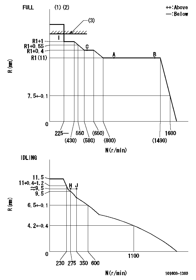
N:Pump speed
R:Rack position (mm)
(1)Torque cam stamping: T1
(2)Tolerance for racks not indicated: +-0.05mm.
(3)RACK LIMIT
----------
T1=D52
----------
----------
T1=D52
----------
Speed control lever angle
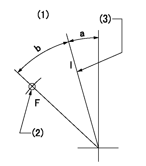
F:Full speed
I:Idle
(1)Accelerator lever
(2)Use the hole at R = aa
(3)Stopper bolt set position 'H'
----------
aa=40mm
----------
a=18.5deg+-5deg b=40.5deg+-3deg
----------
aa=40mm
----------
a=18.5deg+-5deg b=40.5deg+-3deg
Stop lever angle
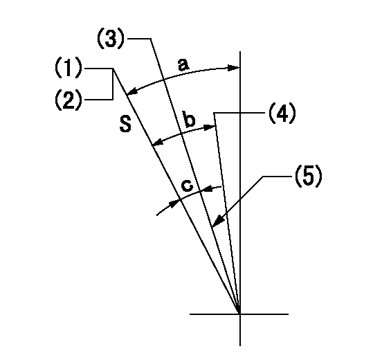
S:Stop the pump.
(1)Set the stopper bolt at pump speed = aa and rack position = bb (non-injection rack position). Confirm non-injection.
(2)After setting the stopper bolt, confirm non-injection at speed cc. Rack position = dd (non-injection rack position).
(3)Rack position = approximately ee (speed lever full, speed = ff).
(4)Free (at delivery)
(5)Normal use set at engine manufacturer.
----------
aa=1450r/min bb=4.7-0.5mm cc=275r/min dd=(6.7)mm ee=15mm ff=0r/min
----------
a=38.5deg+-5deg b=(29deg) c=17deg+-5deg
----------
aa=1450r/min bb=4.7-0.5mm cc=275r/min dd=(6.7)mm ee=15mm ff=0r/min
----------
a=38.5deg+-5deg b=(29deg) c=17deg+-5deg
0000001501 LEVER
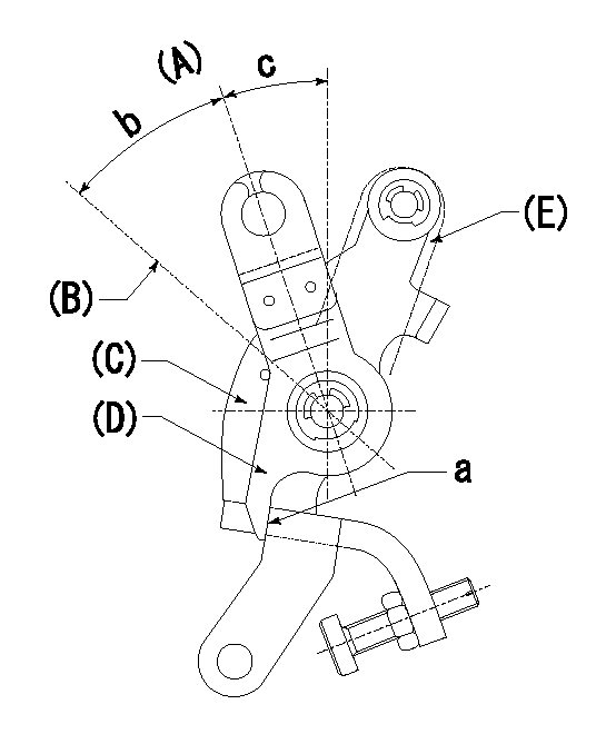
(A) Idle
(B) Full speed
(C) Base lever
(D) Accelerator lever
(E) Accelerator lever delivery position
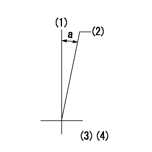
1. Measure speed lever angle
(1)Measure the angle when the accelerator lever (D) contacted the base lever (C) at a.
----------
----------
b=40.5deg+-3deg c=18.5deg+-5deg
----------
----------
b=40.5deg+-3deg c=18.5deg+-5deg
0000001601 ACS
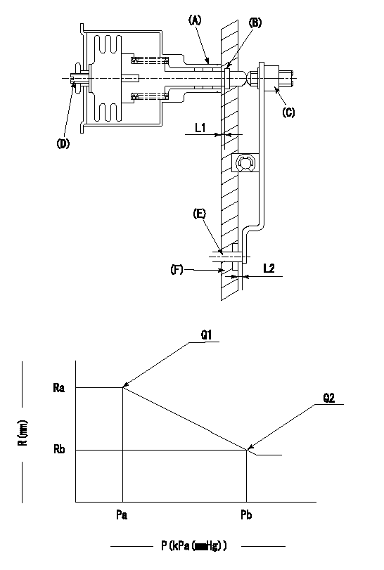
(A) Housing
(B) Snap ring
(C) adjusting screw
(D) Set screw
(E): Push rod
(F) Spacer
1. Adjustment of the aneroid compensator
(1)Adjust with the (D) set screw so that the clearance between the (A) housing and (B) snap ring is L1.
(2)Select the push rod (E) so that the distance from the end surface of the (F) spacer becomes L2.
(3)(C) Turn the screw to adjust the beginning of aneroid compensator operation.
2. Adjustment when mounting the governor.
(1)Set the speed of the pump to N1 r/min and fix the control lever at the full set position.
(2)Adjust using screw C to obtain the performance shown in the graph above.
(3)After final adjustment, confirm that the gap between housing (A) and snapring (B) is L3.
----------
N1=850r/min L1=1.4~1.7mm L2=0.5+-0.5mm L3=0.1~0.5mm
----------
Ra=R1(11)mm Rb=R1-0.3mm Pa=89.8+-2.7kPa(674+-20mmHg) Pb=79.4kPa(596mmHg) Q1=65+-1cm3/1000st Q2=(59)cm3/1000st
----------
N1=850r/min L1=1.4~1.7mm L2=0.5+-0.5mm L3=0.1~0.5mm
----------
Ra=R1(11)mm Rb=R1-0.3mm Pa=89.8+-2.7kPa(674+-20mmHg) Pb=79.4kPa(596mmHg) Q1=65+-1cm3/1000st Q2=(59)cm3/1000st
Timing setting
(1)Pump vertical direction
(2)Position of timer's tooth at No 1 cylinder's beginning of injection
(3)B.T.D.C.: aa
(4)-
----------
aa=16deg
----------
a=(1deg)
----------
aa=16deg
----------
a=(1deg)