Rating:
Information injection-pump assembly
BOSCH
9 400 615 606
9400615606
ZEXEL
101607-1290
1016071290
MITSUBISHI
ME056886
me056886
Service parts 101607-1290 INJECTION-PUMP ASSEMBLY:
1.
_
7.
COUPLING PLATE
8.
_
9.
_
11.
Nozzle and Holder
ME056371
12.
Open Pre:MPa(Kqf/cm2)
21.6{220}

15.
NOZZLE SET
Include in #1:
101607-1290
as INJECTION-PUMP ASSEMBLY
Include in #2:
104746-6607
as _
Cross reference number
BOSCH
9 400 615 606
9400615606
ZEXEL
101607-1290
1016071290
MITSUBISHI
ME056886
me056886
Zexel num
Bosch num
Firm num
Name
101607-1290
9 400 615 606
ME056886 MITSUBISHI
INJECTION-PUMP ASSEMBLY
6D22 * K 14BF INJECTION PUMP ASSY PE6AD PE
6D22 * K 14BF INJECTION PUMP ASSY PE6AD PE
Calibration Data:
Adjustment conditions
Test oil
1404 Test oil ISO4113 or {SAEJ967d}
1404 Test oil ISO4113 or {SAEJ967d}
Test oil temperature
degC
40
40
45
Nozzle and nozzle holder
105780-8140
Bosch type code
EF8511/9A
Nozzle
105780-0000
Bosch type code
DN12SD12T
Nozzle holder
105780-2080
Bosch type code
EF8511/9
Opening pressure
MPa
17.2
Opening pressure
kgf/cm2
175
Injection pipe
Outer diameter - inner diameter - length (mm) mm 6-2-600
Outer diameter - inner diameter - length (mm) mm 6-2-600
Overflow valve
131424-5120
Overflow valve opening pressure
kPa
255
221
289
Overflow valve opening pressure
kgf/cm2
2.6
2.25
2.95
Tester oil delivery pressure
kPa
157
157
157
Tester oil delivery pressure
kgf/cm2
1.6
1.6
1.6
Direction of rotation (viewed from drive side)
Right R
Right R
Injection timing adjustment
Direction of rotation (viewed from drive side)
Right R
Right R
Injection order
1-5-3-6-
2-4
Pre-stroke
mm
4.5
4.45
4.55
Beginning of injection position
Governor side NO.1
Governor side NO.1
Difference between angles 1
Cal 1-5 deg. 60 59.5 60.5
Cal 1-5 deg. 60 59.5 60.5
Difference between angles 2
Cal 1-3 deg. 120 119.5 120.5
Cal 1-3 deg. 120 119.5 120.5
Difference between angles 3
Cal 1-6 deg. 180 179.5 180.5
Cal 1-6 deg. 180 179.5 180.5
Difference between angles 4
Cyl.1-2 deg. 240 239.5 240.5
Cyl.1-2 deg. 240 239.5 240.5
Difference between angles 5
Cal 1-4 deg. 300 299.5 300.5
Cal 1-4 deg. 300 299.5 300.5
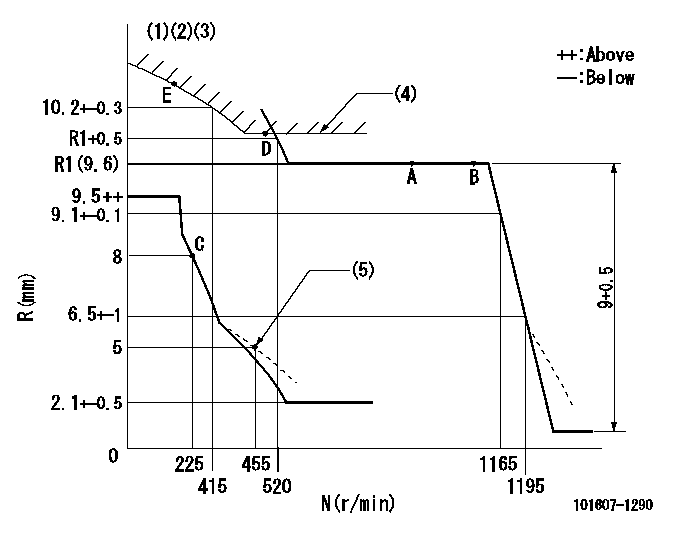
Injection quantity adjustment
Adjusting point
-
Rack position
9.6
Pump speed
r/min
700
700
700
Each cylinder's injection qty
mm3/st.
112
108.6
115.4
Basic
*
Fixing the rack
*
Standard for adjustment of the maximum variation between cylinders
*
Injection quantity adjustment_02
Adjusting point
C
Rack position
8+-0.5
Pump speed
r/min
225
225
225
Each cylinder's injection qty
mm3/st.
18.5
15.7
21.3
Fixing the rack
*
Standard for adjustment of the maximum variation between cylinders
*
Injection quantity adjustment_03
Adjusting point
A
Rack position
R1(9.6)
Pump speed
r/min
700
700
700
Average injection quantity
mm3/st.
112
111
113
Basic
*
Fixing the lever
*
Injection quantity adjustment_04
Adjusting point
B
Rack position
R1(9.6)
Pump speed
r/min
1100
1100
1100
Average injection quantity
mm3/st.
113.5
111
116
Difference in delivery
mm3/st.
9
9
9
Fixing the lever
*
Injection quantity adjustment_05
Adjusting point
E
Rack position
-
Pump speed
r/min
100
100
100
Average injection quantity
mm3/st.
140
120
160
Fixing the lever
*
Remarks
After startup boost setting
After startup boost setting
Timer adjustment
Pump speed
r/min
850--
Advance angle
deg.
0
0
0
Remarks
Start
Start
Timer adjustment_02
Pump speed
r/min
800
Advance angle
deg.
0.5
Timer adjustment_03
Pump speed
r/min
1000
Advance angle
deg.
0.9
0.4
1.4
Timer adjustment_04
Pump speed
r/min
1150
Advance angle
deg.
3
2.5
3.5
Timer adjustment_05
Pump speed
r/min
-
Advance angle
deg.
4
4
5
Remarks
Measure the actual speed, stop
Measure the actual speed, stop
Test data Ex:
Governor adjustment
N:Pump speed
R:Rack position (mm)
(1)Lever ratio: RT
(2)Target shim dimension: TH
(3)Tolerance for racks not indicated: +-0.05mm.
(4)Excess fuel setting for starting: SXL (N = N1)
(5)Damper spring setting
----------
RT=1 TH=2.6mm SXL=9.7+-0.1mm N1=500r/min
----------
----------
RT=1 TH=2.6mm SXL=9.7+-0.1mm N1=500r/min
----------
Speed control lever angle
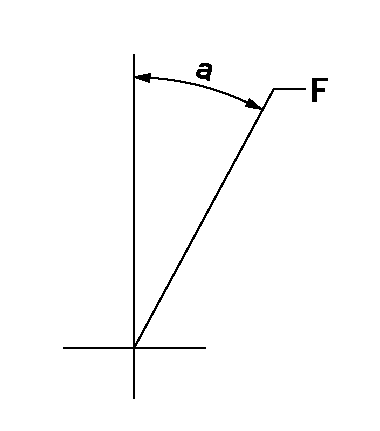
F:Full speed
----------
----------
a=8deg+-5deg
----------
----------
a=8deg+-5deg
0000000901
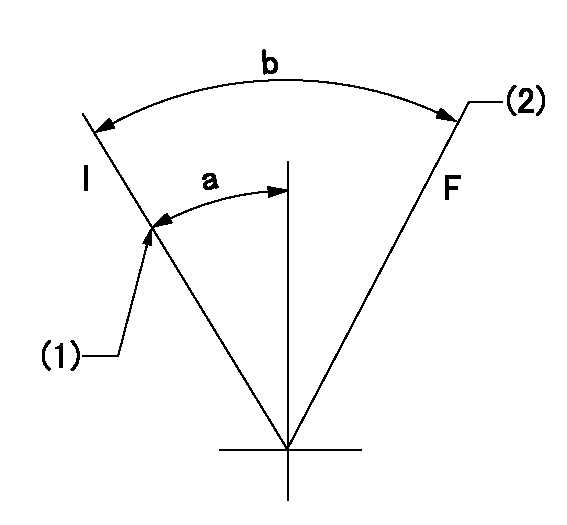
F:Full load
I:Idle
(1)Stopper bolt setting
(2)-
----------
----------
a=24deg+-5deg b=27.5deg+-3deg
----------
----------
a=24deg+-5deg b=27.5deg+-3deg
Stop lever angle
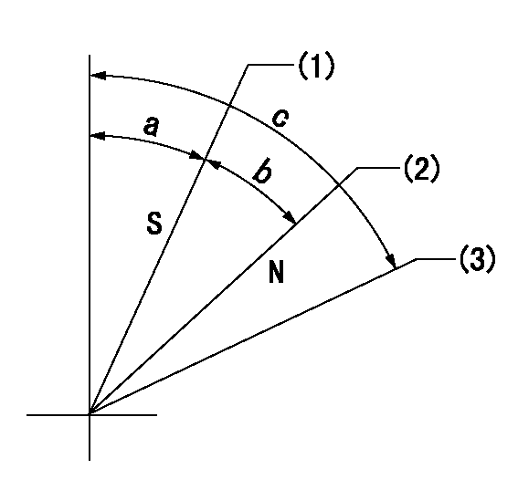
N:Normal
S:Stop
(1)At rack position aa, set the stopper screw.
(2)Rack position bb
(3)Free (at delivery)
----------
aa=5.5-0.5mm bb=16mm
----------
a=12.5deg+5deg-2deg b=34deg+-5deg c=(66.5deg)
----------
aa=5.5-0.5mm bb=16mm
----------
a=12.5deg+5deg-2deg b=34deg+-5deg c=(66.5deg)
0000001501 ACS
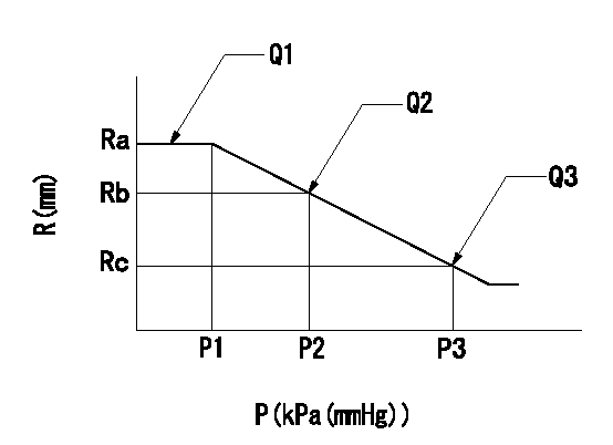
(P) Absolute pressure
(R) Rack position (mm)
1. Adjustment of the aneroid compensator
(1)Screw in the aneroid compensator body and attach the pushrod to the compensator lever so that the performance in the above graph can be obtained. The control lever must be at the full set position N = N1.
----------
N1=700r/min
----------
Ra=9.6mm Rb=9.15mm Rc=8.7mm P1=(88.8)kPa((666)mmHg) P2=(78.5)kPa((589)mmHg) P3=69.3+-0.7kPa(520+-5mmHg) Q1=112+-1cm3/1000st Q2=- Q3=-
----------
N1=700r/min
----------
Ra=9.6mm Rb=9.15mm Rc=8.7mm P1=(88.8)kPa((666)mmHg) P2=(78.5)kPa((589)mmHg) P3=69.3+-0.7kPa(520+-5mmHg) Q1=112+-1cm3/1000st Q2=- Q3=-
0000001601 MICRO SWITCH
Adjustment of the micro-switch
Adjust the bolt to obtain the following lever position when the micro-switch is ON.
(1)Speed N1
(2)Rack position Ra
----------
N1=325+-5r/min Ra=7.3mm
----------
----------
N1=325+-5r/min Ra=7.3mm
----------
Timing setting

(1)Pump vertical direction
(2)Coupling's key groove position at No 1 cylinder's beginning of injection
(3)-
(4)-
----------
----------
a=(7deg)
----------
----------
a=(7deg)
Have questions with 101607-1290?
Group cross 101607-1290 ZEXEL
Mitsubishi
Mitsubishi
Mitsubishi
Mitsubishi
101607-1290
9 400 615 606
ME056886
INJECTION-PUMP ASSEMBLY
6D22
6D22