
Rating:
Information injection-pump assembly
BOSCH
9 400 615 488
9400615488
ZEXEL
101606-6102
1016066102
MITSUBISHI
ME076288
me076288
Service parts 101606-6102 INJECTION-PUMP ASSEMBLY:
1.
_
6.
COUPLING PLATE
7.
COUPLING PLATE
8.
_
9.
_
11.
Nozzle and Holder
12.
Open Pre:MPa(Kqf/cm2)
17.7(180)
15.
NOZZLE SET
Cross reference number
BOSCH
9 400 615 488
9400615488
ZEXEL
101606-6102
1016066102
MITSUBISHI
ME076288
me076288
Zexel num
Bosch num
Firm num
Name
Calibration Data:
Adjustment conditions
Test oil
1404 Test oil ISO4113 or {SAEJ967d}
1404 Test oil ISO4113 or {SAEJ967d}
Test oil temperature
degC
40
40
45
Nozzle and nozzle holder
105780-8140
Bosch type code
EF8511/9A
Nozzle
105780-0000
Bosch type code
DN12SD12T
Nozzle holder
105780-2080
Bosch type code
EF8511/9
Opening pressure
MPa
17.2
Opening pressure
kgf/cm2
175
Injection pipe
Outer diameter - inner diameter - length (mm) mm 6-2-600
Outer diameter - inner diameter - length (mm) mm 6-2-600
Overflow valve
131424-5520
Overflow valve opening pressure
kPa
255
221
289
Overflow valve opening pressure
kgf/cm2
2.6
2.25
2.95
Tester oil delivery pressure
kPa
157
157
157
Tester oil delivery pressure
kgf/cm2
1.6
1.6
1.6
Direction of rotation (viewed from drive side)
Left L
Left L
Injection timing adjustment
Direction of rotation (viewed from drive side)
Left L
Left L
Injection order
1-5-3-6-
2-4
Pre-stroke
mm
3.5
3.45
3.55
Beginning of injection position
Governor side NO.1
Governor side NO.1
Difference between angles 1
Cal 1-5 deg. 60 59.5 60.5
Cal 1-5 deg. 60 59.5 60.5
Difference between angles 2
Cal 1-3 deg. 120 119.5 120.5
Cal 1-3 deg. 120 119.5 120.5
Difference between angles 3
Cal 1-6 deg. 180 179.5 180.5
Cal 1-6 deg. 180 179.5 180.5
Difference between angles 4
Cyl.1-2 deg. 240 239.5 240.5
Cyl.1-2 deg. 240 239.5 240.5
Difference between angles 5
Cal 1-4 deg. 300 299.5 300.5
Cal 1-4 deg. 300 299.5 300.5
Injection quantity adjustment
Adjusting point
-
Rack position
11.1
Pump speed
r/min
850
850
850
Each cylinder's injection qty
mm3/st.
68
66
70
Basic
*
Fixing the rack
*
Standard for adjustment of the maximum variation between cylinders
*
Injection quantity adjustment_02
Adjusting point
H
Rack position
9.5+-0.5
Pump speed
r/min
275
275
275
Each cylinder's injection qty
mm3/st.
8.7
8.2
9.2
Fixing the rack
*
Standard for adjustment of the maximum variation between cylinders
*
Injection quantity adjustment_03
Adjusting point
A
Rack position
R1(11.1)
Pump speed
r/min
850
850
850
Average injection quantity
mm3/st.
68
67
69
Basic
*
Fixing the lever
*
Injection quantity adjustment_04
Adjusting point
B
Rack position
R1+0.2
Pump speed
r/min
1400
1400
1400
Average injection quantity
mm3/st.
79.9
75.9
83.9
Fixing the lever
*
Injection quantity adjustment_05
Adjusting point
D
Rack position
R1+0.2
Pump speed
r/min
500
500
500
Average injection quantity
mm3/st.
52.4
48.4
56.4
Fixing the lever
*
Injection quantity adjustment_06
Adjusting point
I
Rack position
-
Pump speed
r/min
100
100
100
Average injection quantity
mm3/st.
85
65
105
Fixing the lever
*
Rack limit
*
Timer adjustment
Pump speed
r/min
1150
Advance angle
deg.
0.5
Timer adjustment_02
Pump speed
r/min
1250
Advance angle
deg.
2.5
2
3
Timer adjustment_03
Pump speed
r/min
1350
Advance angle
deg.
5
4.5
5.5
Remarks
Finish
Finish
Test data Ex:
Governor adjustment
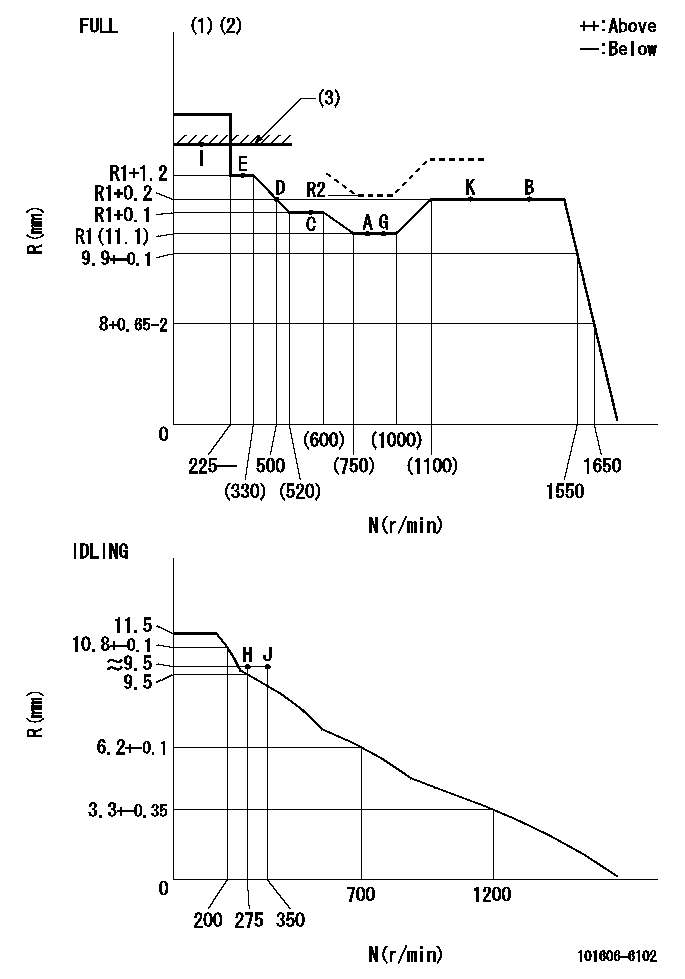
N:Pump speed
R:Rack position (mm)
(1)Torque cam stamping: T1
(2)Tolerance for racks not indicated: +-0.05mm.
(3)RACK LIMIT
----------
T1=C85
----------
----------
T1=C85
----------
Speed control lever angle
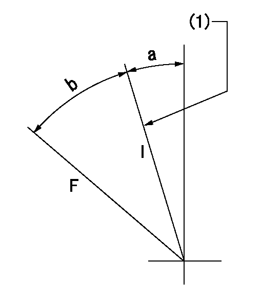
F:Full speed
I:Idle
(1)Stopper bolt set position 'H'
----------
----------
a=18.5deg+-5deg b=39deg+-3deg
----------
----------
a=18.5deg+-5deg b=39deg+-3deg
Stop lever angle
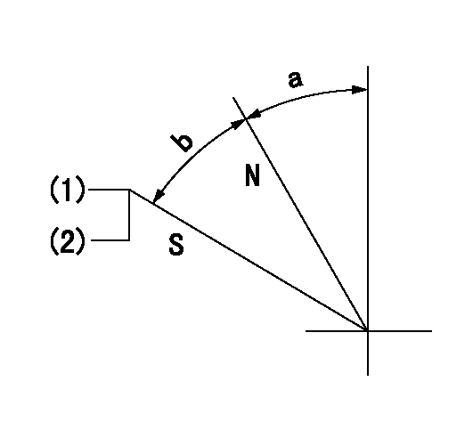
N:Pump normal
S:Stop the pump.
(1)Set the stopper bolt at pump speed = aa and rack position = bb (non-injection rack position). Confirm non-injection.
(2)After setting the stopper bolt, confirm non-injection at speed cc. Rack position = dd (non-injection rack position).
----------
aa=1400r/min bb=(6.5)mm cc=275r/min dd=(6.5)mm
----------
a=11.5deg+-5deg b=(27deg)+-5deg
----------
aa=1400r/min bb=(6.5)mm cc=275r/min dd=(6.5)mm
----------
a=11.5deg+-5deg b=(27deg)+-5deg
0000001501 MICRO SWITCH
Adjustment of the micro-switch
Adjust the bolt to obtain the following lever position when the micro-switch is ON.
(1)Speed N1
(2)Rack position Ra
----------
N1=400r/min Ra=9.2+-0.1mm
----------
----------
N1=400r/min Ra=9.2+-0.1mm
----------
0000001601 LEVER
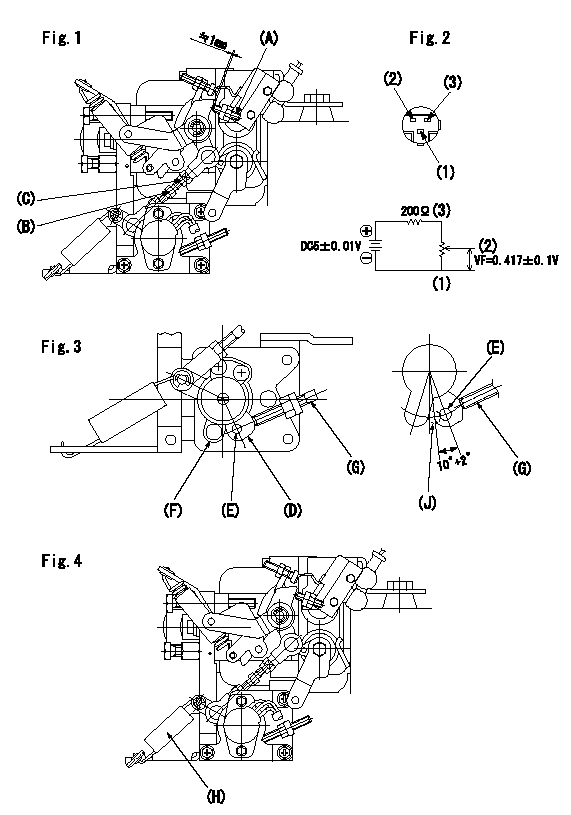
(A) Accelerator lever stopper bolt
(B) Link
(c) Nut
(D) Lever
(E) Pin
(f) lever
(G) Stopper bolt
(H) Return spring
(J) Pin (E) contacts lever.
(K) Load sensor terminal
(1)Black
(2)Blue-yellow
(3)Blue-red
Setting the accelerator lever angle, load sensor adjustment
1. Accelerator lever setting method
(1)Position the speed lever against the idle stopper bolt and fix.
(2)Screw in the accelerator lever stopper bolt (A) and back off the stopper bolt (A) from the position where the accelerator lever pin contacts the speed lever and set. (Gap: approx. 1 mm)
Tightening torque: 4.9~7 N.m {0.5~0.7 kgf.m}
2. Load sensor adjustment (See fig 1)
(1)Load sensor output measuring circuit
Apply DC5+-0.01V to the load sensor terminals and measure the output voltage.
(2)Load sensor output adjustment procedure
Hold the speed lever against the full side stopper bolt and fix. Adjust the load sensor output voltage to VF = 0.417+-0.1 V using the link (B) and then fix temporarily using nut (C).
Turn the speed lever from the idle side to the full side and confirm that output voltage VF = 0.417+-0.1 V is obtained. Confirm several times and then fix using nut (C).
Tightening torque: 3.4~4.9 N.m {0.35~0.5 kgf.m}
3. Setting the step motor's idle side stopper bolt
After adjustment in previous 1 and 2, position speed lever against idle stopper bolt and fix. Then, screw in stopper bolt G until step motor lever D's pin E contacts lever F. Back off 10+2 deg (approx. 3.5 mm) from this position and fix G. (See fig. 3)
4. Speed lever return confirmation
(1)Remove return spring (H) and confirm that the speed lever is returned to the idle position by the torsion spring.
(2)Reinstall the return spring (H) in its original position.
----------
----------
----------
----------
0000001701 TAMPER PROOF
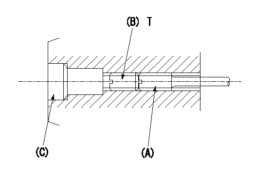
1. Method for setting tamperproof proofing
(1)After governor adjustment (torque cam phase adjustment), move the load lever to increase the full rack position to Ra.
(2)At speed N1 screw in screw (A) to obtain the rack position (actual measurement: Rb) for injection quantity Q1.
(3)Temporarily caulk using the tip of a screwdriver
(4)Confirm that the rack at that time is at Rc.
(5)Lock using setscrew (B). (Tightening torque = T)
(6)Next, coat (C) with adhesive and then pressfit.
(7)Then, readjust the full rack position using the load lever.
----------
N1=900r/min Q1=80.1+-1mm3/st Ra=(0.4)mm Rb=R2mm Rc=R2mm
----------
T=3.4~4.9N-m(0.35~0.5Kgf-m)
----------
N1=900r/min Q1=80.1+-1mm3/st Ra=(0.4)mm Rb=R2mm Rc=R2mm
----------
T=3.4~4.9N-m(0.35~0.5Kgf-m)
Timing setting

(1)Pump vertical direction
(2)Position of timer's tooth at No 1 cylinder's beginning of injection
(3)B.T.D.C.: aa
(4)-
----------
aa=12deg
----------
a=(1deg)
----------
aa=12deg
----------
a=(1deg)