
Rating:
Information injection-pump assembly
ZEXEL
101603-9660
1016039660
Cross reference number
ZEXEL
101603-9660
1016039660
Zexel num
Bosch num
Firm num
Name
101603-9660
INJECTION-PUMP ASSEMBLY
Calibration Data:
Adjustment conditions
Test oil
1404 Test oil ISO4113 or {SAEJ967d}
1404 Test oil ISO4113 or {SAEJ967d}
Test oil temperature
degC
40
40
45
Nozzle and nozzle holder
105780-8140
Bosch type code
EF8511/9A
Nozzle
105780-0000
Bosch type code
DN12SD12T
Nozzle holder
105780-2080
Bosch type code
EF8511/9
Opening pressure
MPa
17.2
Opening pressure
kgf/cm2
175
Injection pipe
Outer diameter - inner diameter - length (mm) mm 6-2-600
Outer diameter - inner diameter - length (mm) mm 6-2-600
Overflow valve
134424-1520
Overflow valve opening pressure
kPa
162
147
177
Overflow valve opening pressure
kgf/cm2
1.65
1.5
1.8
Tester oil delivery pressure
kPa
157
157
157
Tester oil delivery pressure
kgf/cm2
1.6
1.6
1.6
Direction of rotation (viewed from drive side)
Right R
Right R
Injection timing adjustment
Direction of rotation (viewed from drive side)
Right R
Right R
Injection order
1-4-2-6-
3-5
Pre-stroke
mm
3.4
3.35
3.45
Beginning of injection position
Drive side NO.1
Drive side NO.1
Difference between angles 1
Cal 1-4 deg. 60 59.5 60.5
Cal 1-4 deg. 60 59.5 60.5
Difference between angles 2
Cyl.1-2 deg. 120 119.5 120.5
Cyl.1-2 deg. 120 119.5 120.5
Difference between angles 3
Cal 1-6 deg. 180 179.5 180.5
Cal 1-6 deg. 180 179.5 180.5
Difference between angles 4
Cal 1-3 deg. 240 239.5 240.5
Cal 1-3 deg. 240 239.5 240.5
Difference between angles 5
Cal 1-5 deg. 300 299.5 300.5
Cal 1-5 deg. 300 299.5 300.5
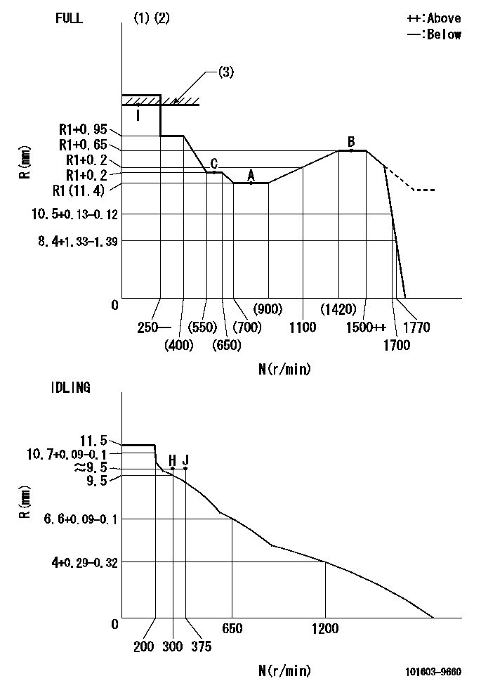
Injection quantity adjustment
Adjusting point
-
Rack position
11.4
Pump speed
r/min
800
800
800
Average injection quantity
mm3/st.
63
61.4
64.6
Max. variation between cylinders
%
0
-3.5
3.5
Basic
*
Fixing the rack
*
Standard for adjustment of the maximum variation between cylinders
*
Injection quantity adjustment_02
Adjusting point
H
Rack position
9.5+-0.5
Pump speed
r/min
300
300
300
Average injection quantity
mm3/st.
9.2
7.4
11
Max. variation between cylinders
%
0
-10
10
Fixing the rack
*
Standard for adjustment of the maximum variation between cylinders
*
Injection quantity adjustment_03
Adjusting point
A
Rack position
R1(11.4)
Pump speed
r/min
800
800
800
Average injection quantity
mm3/st.
63
62
64
Basic
*
Fixing the lever
*
Injection quantity adjustment_04
Adjusting point
B
Rack position
R1+0.65
Pump speed
r/min
1500
1500
1500
Average injection quantity
mm3/st.
84.5
80.5
88.5
Fixing the lever
*
Injection quantity adjustment_05
Adjusting point
C
Rack position
R1+0.2
Pump speed
r/min
600
600
600
Average injection quantity
mm3/st.
58
54.8
61.2
Fixing the lever
*
Injection quantity adjustment_06
Adjusting point
I
Rack position
-
Pump speed
r/min
100
100
100
Average injection quantity
mm3/st.
82
82
92
Fixing the lever
*
Rack limit
*
Test data Ex:
Governor adjustment
N:Pump speed
R:Rack position (mm)
(1)Torque cam stamping: T1
(2)Tolerance for racks not indicated: +-0.05mm.
(3)RACK LIMIT
----------
T1=E88
----------
----------
T1=E88
----------
Timer adjustment
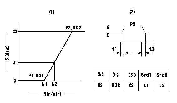
(1)Adjusting range
(2)Step response time
(N): Speed of the pump
(L): Load
(theta) Advance angle
(Srd1) Step response time 1
(Srd2) Step response time 2
1. Adjusting conditions for the variable timer
(1)Adjust the clearance between the pickup and the protrusion to L.
----------
L=1.5+-0.2mm N3=800r/min C3=(6.5deg) t1=2--sec. t2=2--sec.
----------
N1=1200++r/min N2=1400r/min P1=0kPa(0kgf/cm2) P2=392kPa(4kgf/cm2) C1=2.5--deg C2=6.5+-0.4deg R01=0/4load R02=4/4load
----------
L=1.5+-0.2mm N3=800r/min C3=(6.5deg) t1=2--sec. t2=2--sec.
----------
N1=1200++r/min N2=1400r/min P1=0kPa(0kgf/cm2) P2=392kPa(4kgf/cm2) C1=2.5--deg C2=6.5+-0.4deg R01=0/4load R02=4/4load
Speed control lever angle
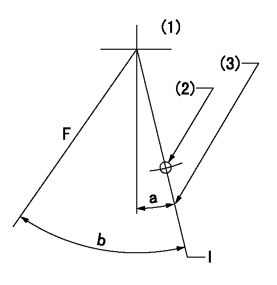
F:Full speed
I:Idle
(1)Bottom lever
(2)Use the hole at R = aa
(3)Stopper bolt set position 'H'
----------
aa=39mm
----------
a=26.5deg+-5deg b=40deg+-3deg
----------
aa=39mm
----------
a=26.5deg+-5deg b=40deg+-3deg
Stop lever angle
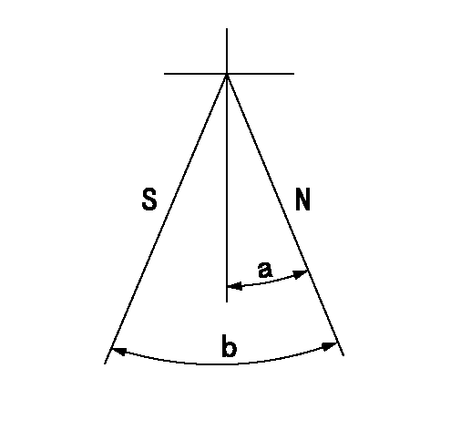
N:Pump normal
S:Stop the pump.
----------
----------
a=20deg+-5deg b=40deg+-5deg
----------
----------
a=20deg+-5deg b=40deg+-5deg
0000001501 RACK SENSOR
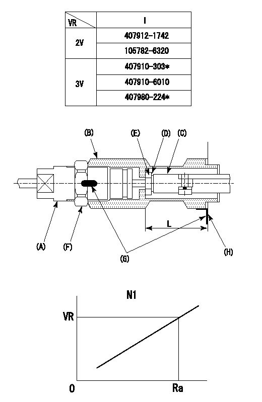
(VR) measurement voltage
(I) Part number of the control unit
(G) Apply red paint.
(H): End surface of the pump
1. Rack limit adjustment
(1)Fix the rack at the rack limit position Ra.
(2)Install the shim (D) to the rod (C) and tighten nut (E).
(3)Select a shim (D) so that the distance between the end surface of the pump and the nut (E) is L.
(4)Release the rack fixing and mount the joint (B) and fix.
(5)At this time, confirm that the shim (D) does not interfere with the joint (B).
2. Rack sensor adjustment (-0420)
(1)Screw in the bobbin (A) until it contacts the joint (B).
(2)Fix the speed control lever at the full side.
(3)Set the speed to N1 r/min.
(4)Adjust the depth that the bobbin (A) is screwed in so that the control unit's rack sensor output voltage is VR+-0.01 (V), then tighten the nut (F).
(5)Adjust the bobbin (A) so that the rack sensor's output voltage is VR.
(6)Apply G at two places.
Connecting part between the joint (B) and the nut (F)
Connecting part between the joint (B) and the end surface of the pump (H)
----------
L=33-0.2mm N1=1500r/min Ra=R1(11.4)+0.65mm
----------
----------
L=33-0.2mm N1=1500r/min Ra=R1(11.4)+0.65mm
----------
0000001601 LEVER
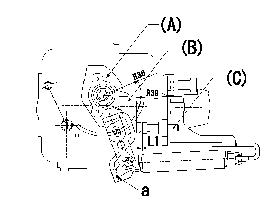
(a) Speed lever
(B) Accelerator lever
(C) Accelerator lever stopper bolt
1. Accelerator lever setting method
With the speed lever in the idling position, back off the accelerator lever stopper bolt L1 from where it contacts point a. (Back off 1+0.5 turns and set.)
----------
L1=1+0.5mm
----------
----------
L1=1+0.5mm
----------
Timing setting

(1)Pump vertical direction
(2)Position of timer's threaded hole at the No. 1 cylinder's beginning of injection
(3)-
(4)-
----------
----------
a=(60deg)
----------
----------
a=(60deg)
Have questions with 101603-9660?
Group cross 101603-9660 ZEXEL
Nissan-Diesel
Nissan-Diesel
Nissan-Diesel
Nissan-Diesel
101603-9660
INJECTION-PUMP ASSEMBLY