Rating:
Information injection-pump assembly
ZEXEL
101603-8681
1016038681
ISUZU
8943959691
8943959691
Service parts 101603-8681 INJECTION-PUMP ASSEMBLY:
1.
_
7.
COUPLING PLATE
8.
_
9.
_
11.
Nozzle and Holder
8-94395-498-2
12.
Open Pre:MPa(Kqf/cm2)
18.1{185}
15.
NOZZLE SET
Cross reference number
ZEXEL
101603-8681
1016038681
ISUZU
8943959691
8943959691
Zexel num
Bosch num
Firm num
Name
Calibration Data:
Adjustment conditions
Test oil
1404 Test oil ISO4113 or {SAEJ967d}
1404 Test oil ISO4113 or {SAEJ967d}
Test oil temperature
degC
40
40
45
Nozzle and nozzle holder
105780-8260
Bosch type code
9 430 610 133
Nozzle
105780-0120
Bosch type code
1 688 901 990
Nozzle holder
105780-2190
Opening pressure
MPa
18
Opening pressure
kgf/cm2
184
Injection pipe
Outer diameter - inner diameter - length (mm) mm 6-2-600
Outer diameter - inner diameter - length (mm) mm 6-2-600
Overflow valve
131424-4920
Overflow valve opening pressure
kPa
127
107
147
Overflow valve opening pressure
kgf/cm2
1.3
1.1
1.5
Tester oil delivery pressure
kPa
255
255
255
Tester oil delivery pressure
kgf/cm2
2.6
2.6
2.6
Direction of rotation (viewed from drive side)
Left L
Left L
Injection timing adjustment
Direction of rotation (viewed from drive side)
Left L
Left L
Injection order
1-5-3-6-
2-4
Pre-stroke
mm
4
3.95
4.05
Beginning of injection position
Governor side NO.1
Governor side NO.1
Difference between angles 1
Cal 1-5 deg. 60 59.5 60.5
Cal 1-5 deg. 60 59.5 60.5
Difference between angles 2
Cal 1-3 deg. 120 119.5 120.5
Cal 1-3 deg. 120 119.5 120.5
Difference between angles 3
Cal 1-6 deg. 180 179.5 180.5
Cal 1-6 deg. 180 179.5 180.5
Difference between angles 4
Cyl.1-2 deg. 240 239.5 240.5
Cyl.1-2 deg. 240 239.5 240.5
Difference between angles 5
Cal 1-4 deg. 300 299.5 300.5
Cal 1-4 deg. 300 299.5 300.5
Injection quantity adjustment
Adjusting point
-
Rack position
11.6
Pump speed
r/min
850
850
850
Average injection quantity
mm3/st.
91.5
89.9
93.1
Max. variation between cylinders
%
0
-2.5
2.5
Basic
*
Fixing the rack
*
Standard for adjustment of the maximum variation between cylinders
*
Injection quantity adjustment_02
Adjusting point
Z
Rack position
9.6+-0.5
Pump speed
r/min
240
240
240
Average injection quantity
mm3/st.
9.4
8.1
10.7
Max. variation between cylinders
%
0
-14
14
Fixing the rack
*
Standard for adjustment of the maximum variation between cylinders
*
Injection quantity adjustment_03
Adjusting point
A
Rack position
R1(11.6)
Pump speed
r/min
850
850
850
Average injection quantity
mm3/st.
91.5
90.5
92.5
Basic
*
Fixing the lever
*
Injection quantity adjustment_04
Adjusting point
B
Rack position
R1+0.95
Pump speed
r/min
1425
1425
1425
Average injection quantity
mm3/st.
100.5
96.5
104.5
Fixing the lever
*
Injection quantity adjustment_05
Adjusting point
C
Rack position
R1+0.6
Pump speed
r/min
1150
1150
1150
Average injection quantity
mm3/st.
98.5
94.5
102.5
Fixing the lever
*
Injection quantity adjustment_06
Adjusting point
I
Rack position
-
Pump speed
r/min
150
150
150
Average injection quantity
mm3/st.
130
130
138
Fixing the lever
*
Rack limit
*
Timer adjustment
Pump speed
r/min
905--
Advance angle
deg.
0
0
0
Load
0/4
Remarks
Start
Start
Timer adjustment_02
Pump speed
r/min
855
Advance angle
deg.
0.3
Load
0/4
Timer adjustment_03
Pump speed
r/min
(900)
Advance angle
deg.
0
0
0
Load
4/4
Timer adjustment_04
Pump speed
r/min
1425
Advance angle
deg.
5.5
5
6
Load
4/4
Remarks
Finish
Finish
Test data Ex:
Governor adjustment
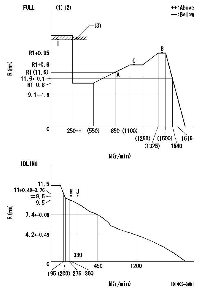
N:Pump speed
R:Rack position (mm)
(1)Torque cam stamping: T1
(2)Tolerance for racks not indicated: +-0.05mm.
(3)RACK LIMIT
----------
T1=K97
----------
----------
T1=K97
----------
Speed control lever angle
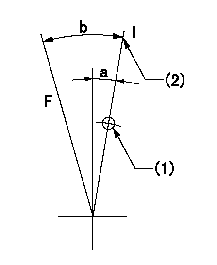
F:Full speed
I:Idle
(1)Use the hole at R = aa
(2)Stopper bolt set position 'H'
----------
aa=35mm
----------
a=13deg+-5deg b=38deg+-3deg
----------
aa=35mm
----------
a=13deg+-5deg b=38deg+-3deg
Stop lever angle
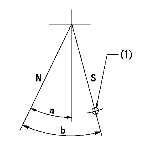
N:Pump normal
S:Stop the pump.
(1)Use the hole at R = aa
----------
aa=46.5mm
----------
a=34.5deg+-5deg b=40deg+-5deg
----------
aa=46.5mm
----------
a=34.5deg+-5deg b=40deg+-5deg
0000001501 AIR CYLINDER
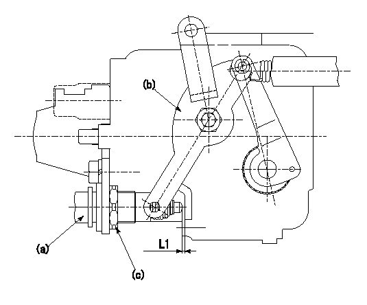
(a) Air cylinder
(b) Speed lever
(c) Lock nut
1. Air cylinder adjustment procedure
(1)Fix the speed lever (b) at the idle side.
(2)Screw in the air cylinder (a)
(3)Set the clearance between the speed lever (b) and the air cylinder (a) to approximately L1.
----------
L1=1mm
----------
----------
L1=1mm
----------
Timing setting
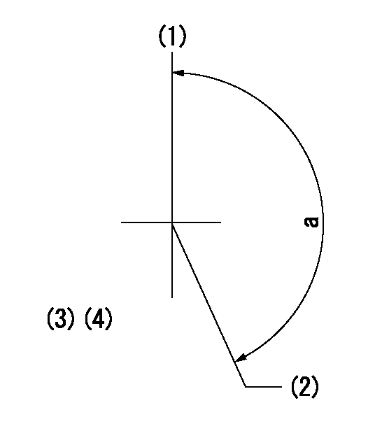
(1)Pump vertical direction
(2)Position of timer's threaded hole at the No. 1 cylinder's beginning of injection
(3)B.T.D.C.: aa
(4)-
----------
aa=7deg
----------
a=(150deg)
----------
aa=7deg
----------
a=(150deg)