Rating:
Information injection-pump assembly
BOSCH
9 400 615 255
9400615255
ZEXEL
101603-8260
1016038260
ISUZU
1156029090
1156029090
Service parts 101603-8260 INJECTION-PUMP ASSEMBLY:
1.
_
7.
COUPLING PLATE
8.
_
9.
_
11.
Nozzle and Holder
1-15300-307-3
12.
Open Pre:MPa(Kqf/cm2)
18.1{185}/22.1{225}
15.
NOZZLE SET
Cross reference number
BOSCH
9 400 615 255
9400615255
ZEXEL
101603-8260
1016038260
ISUZU
1156029090
1156029090
Zexel num
Bosch num
Firm num
Name
101603-8260
9 400 615 255
1156029090 ISUZU
INJECTION-PUMP ASSEMBLY
6BG1-MTC K 14BF INJECTION PUMP ASSY PE6AD PE
6BG1-MTC K 14BF INJECTION PUMP ASSY PE6AD PE
Calibration Data:
Adjustment conditions
Test oil
1404 Test oil ISO4113 or {SAEJ967d}
1404 Test oil ISO4113 or {SAEJ967d}
Test oil temperature
degC
40
40
45
Nozzle and nozzle holder
105780-8140
Bosch type code
EF8511/9A
Nozzle
105780-0000
Bosch type code
DN12SD12T
Nozzle holder
105780-2080
Bosch type code
EF8511/9
Opening pressure
MPa
17.2
Opening pressure
kgf/cm2
175
Injection pipe
Outer diameter - inner diameter - length (mm) mm 6-2-600
Outer diameter - inner diameter - length (mm) mm 6-2-600
Overflow valve
131424-4920
Overflow valve opening pressure
kPa
127
107
147
Overflow valve opening pressure
kgf/cm2
1.3
1.1
1.5
Tester oil delivery pressure
kPa
157
157
157
Tester oil delivery pressure
kgf/cm2
1.6
1.6
1.6
Direction of rotation (viewed from drive side)
Right R
Right R
Injection timing adjustment
Direction of rotation (viewed from drive side)
Right R
Right R
Injection order
1-5-3-6-
2-4
Pre-stroke
mm
3.6
3.55
3.65
Beginning of injection position
Drive side NO.1
Drive side NO.1
Difference between angles 1
Cal 1-5 deg. 60 59.5 60.5
Cal 1-5 deg. 60 59.5 60.5
Difference between angles 2
Cal 1-3 deg. 120 119.5 120.5
Cal 1-3 deg. 120 119.5 120.5
Difference between angles 3
Cal 1-6 deg. 180 179.5 180.5
Cal 1-6 deg. 180 179.5 180.5
Difference between angles 4
Cyl.1-2 deg. 240 239.5 240.5
Cyl.1-2 deg. 240 239.5 240.5
Difference between angles 5
Cal 1-4 deg. 300 299.5 300.5
Cal 1-4 deg. 300 299.5 300.5
Injection quantity adjustment
Adjusting point
A
Rack position
10.3
Pump speed
r/min
1350
1350
1350
Average injection quantity
mm3/st.
144.5
142.9
146.1
Max. variation between cylinders
%
0
-2.5
2.5
Basic
*
Fixing the lever
*
Boost pressure
kPa
127
127
Boost pressure
mmHg
950
950
Injection quantity adjustment_02
Adjusting point
B
Rack position
4.4+-0.5
Pump speed
r/min
265
265
265
Average injection quantity
mm3/st.
13.5
12.2
14.8
Max. variation between cylinders
%
0
-14
14
Fixing the rack
*
Boost pressure
kPa
0
0
0
Boost pressure
mmHg
0
0
0
Boost compensator adjustment
Pump speed
r/min
550
550
550
Rack position
8
Boost pressure
kPa
40
37.3
42.7
Boost pressure
mmHg
300
280
320
Boost compensator adjustment_02
Pump speed
r/min
550
550
550
Rack position
(10.3)
Boost pressure
kPa
113
113
113
Boost pressure
mmHg
850
850
850
Timer adjustment
Pump speed
r/min
1350++
Advance angle
deg.
0
0
0
Remarks
Do not advance until starting N = 1350/
Do not advance until starting N = 1350/
Timer adjustment_02
Pump speed
r/min
-
Advance angle
deg.
1
1
1
Remarks
Measure the actual speed, stop
Measure the actual speed, stop
Test data Ex:
Governor adjustment
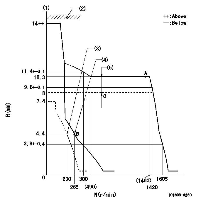
N:Pump speed
R:Rack position (mm)
(1)Target notch: K
(2)Excess fuel lever does not operate.
(3)Set idle sub-spring
(4)Main spring setting
(5)Boost compensator stroke: BCL
----------
K=14 BCL=(2.3)+-0.1mm
----------
----------
K=14 BCL=(2.3)+-0.1mm
----------
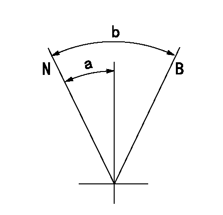
Speed control lever angle
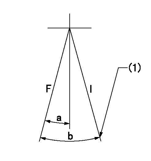
F:Full speed
I:Idle
(1)Stopper bolt setting
----------
----------
a=(28deg)+-5deg b=(33deg)+-5deg
----------
----------
a=(28deg)+-5deg b=(33deg)+-5deg
Stop lever angle
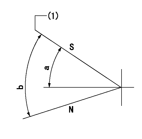
N:Pump normal
S:Stop the pump.
(1)Pump speed aa and rack position bb (to be sealed at delivery)
----------
aa=0r/min bb=1-0.2mm
----------
a=32deg+-5deg b=(55deg)
----------
aa=0r/min bb=1-0.2mm
----------
a=32deg+-5deg b=(55deg)
0000001101
N:Normal
B:When boosted
----------
----------
a=(15deg) b=(30deg)
----------
----------
a=(15deg) b=(30deg)
Timing setting

(1)Pump vertical direction
(2)Position of timer's threaded hole at No 1 cylinder's beginning of injection
(3)B.T.D.C.: aa
(4)-
----------
aa=13deg
----------
a=(60deg)
----------
aa=13deg
----------
a=(60deg)
Have questions with 101603-8260?
Group cross 101603-8260 ZEXEL
Isuzu
Isuzu
101603-8260
9 400 615 255
1156029090
INJECTION-PUMP ASSEMBLY
6BG1-MTC
6BG1-MTC