
Rating:
Information injection-pump assembly
ZEXEL
101603-4230
1016034230
ISUZU
1156018992
1156018992
Cross reference number
ZEXEL
101603-4230
1016034230
ISUZU
1156018992
1156018992
Zexel num
Bosch num
Firm num
Name
101603-4230
1156018992 ISUZU
INJECTION-PUMP ASSEMBLY
6BD1 * K
6BD1 * K
Calibration Data:
Adjustment conditions
Test oil
1404 Test oil ISO4113 or {SAEJ967d}
1404 Test oil ISO4113 or {SAEJ967d}
Test oil temperature
degC
40
40
45
Nozzle and nozzle holder
105780-8140
Bosch type code
EF8511/9A
Nozzle
105780-0000
Bosch type code
DN12SD12T
Nozzle holder
105780-2080
Bosch type code
EF8511/9
Opening pressure
MPa
17.2
Opening pressure
kgf/cm2
175
Injection pipe
Outer diameter - inner diameter - length (mm) mm 6-2-600
Outer diameter - inner diameter - length (mm) mm 6-2-600
Overflow valve
132424-0620
Overflow valve opening pressure
kPa
157
123
191
Overflow valve opening pressure
kgf/cm2
1.6
1.25
1.95
Tester oil delivery pressure
kPa
157
157
157
Tester oil delivery pressure
kgf/cm2
1.6
1.6
1.6
Direction of rotation (viewed from drive side)
Right R
Right R
Injection timing adjustment
Direction of rotation (viewed from drive side)
Right R
Right R
Injection order
1-5-3-6-
2-4
Pre-stroke
mm
3.6
3.55
3.65
Beginning of injection position
Drive side NO.1
Drive side NO.1
Difference between angles 1
Cal 1-5 deg. 60 59.5 60.5
Cal 1-5 deg. 60 59.5 60.5
Difference between angles 2
Cal 1-3 deg. 120 119.5 120.5
Cal 1-3 deg. 120 119.5 120.5
Difference between angles 3
Cal 1-6 deg. 180 179.5 180.5
Cal 1-6 deg. 180 179.5 180.5
Difference between angles 4
Cyl.1-2 deg. 240 239.5 240.5
Cyl.1-2 deg. 240 239.5 240.5
Difference between angles 5
Cal 1-4 deg. 300 299.5 300.5
Cal 1-4 deg. 300 299.5 300.5
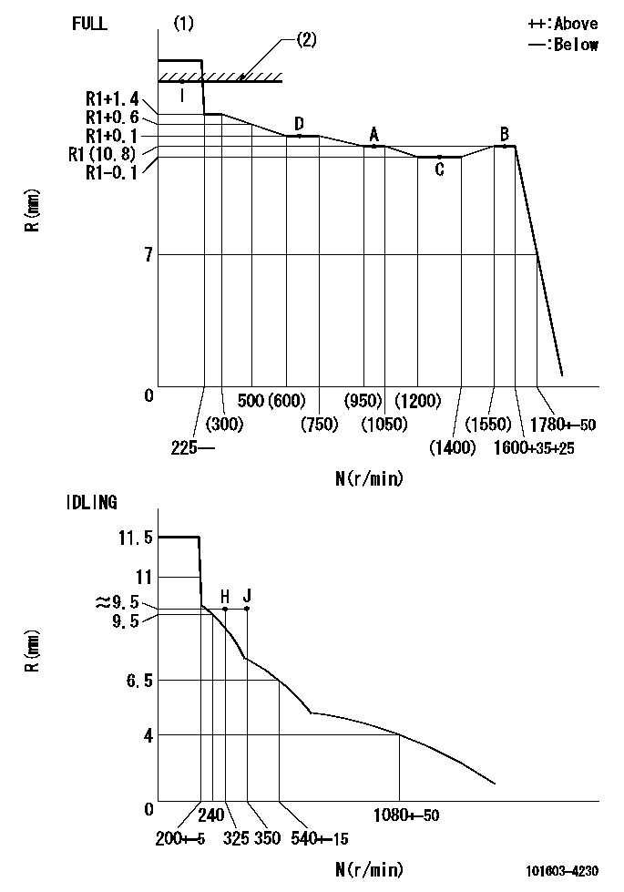
Injection quantity adjustment
Adjusting point
-
Rack position
10.8
Pump speed
r/min
1000
1000
1000
Average injection quantity
mm3/st.
58.6
57
60.2
Max. variation between cylinders
%
0
-2.5
2.5
Basic
*
Fixing the rack
*
Standard for adjustment of the maximum variation between cylinders
*
Injection quantity adjustment_02
Adjusting point
H
Rack position
9.5+-0.5
Pump speed
r/min
325
325
325
Average injection quantity
mm3/st.
8.7
7.4
10
Max. variation between cylinders
%
0
-14
14
Fixing the rack
*
Standard for adjustment of the maximum variation between cylinders
*
Injection quantity adjustment_03
Adjusting point
A
Rack position
R1(10.8)
Pump speed
r/min
1000
1000
1000
Average injection quantity
mm3/st.
58.6
57.6
59.6
Basic
*
Fixing the lever
*
Injection quantity adjustment_04
Adjusting point
B
Rack position
R1(10.8)
Pump speed
r/min
1600
1600
1600
Average injection quantity
mm3/st.
60.2
58.6
61.8
Fixing the lever
*
Injection quantity adjustment_05
Adjusting point
C
Rack position
R1-0.1
Pump speed
r/min
1300
1300
1300
Average injection quantity
mm3/st.
60.4
58.8
62
Fixing the lever
*
Injection quantity adjustment_06
Adjusting point
D
Rack position
R1+0.1
Pump speed
r/min
650
650
650
Average injection quantity
mm3/st.
48.8
47.2
50.4
Fixing the lever
*
Injection quantity adjustment_07
Adjusting point
I
Rack position
R2
Pump speed
r/min
150
150
150
Average injection quantity
mm3/st.
58.5
58.5
63.5
Fixing the lever
*
Rack limit
*
Timer adjustment
Pump speed
r/min
1050--
Advance angle
deg.
0
0
0
Remarks
Start
Start
Timer adjustment_02
Pump speed
r/min
1000
Advance angle
deg.
0.5
Timer adjustment_03
Pump speed
r/min
1300
Advance angle
deg.
1.8
1.3
2.3
Timer adjustment_04
Pump speed
r/min
1600
Advance angle
deg.
4
3.5
4.5
Remarks
Finish
Finish
Test data Ex:
Governor adjustment
N:Pump speed
R:Rack position (mm)
(1)Torque cam stamping: T1
(2)RACK LIMIT: RAL
----------
T1=A35 RAL=R2mm
----------
----------
T1=A35 RAL=R2mm
----------
Speed control lever angle
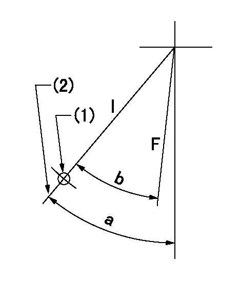
F:Full speed
I:Idle
(1)Use the hole at R = aa
(2)Stopper bolt set position 'H'
----------
aa=35mm
----------
a=39deg+-5deg b=(38deg)+-3deg
----------
aa=35mm
----------
a=39deg+-5deg b=(38deg)+-3deg
Stop lever angle
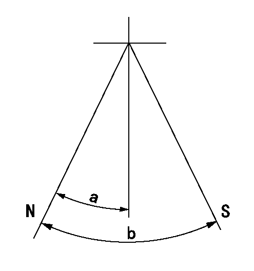
N:Pump normal
S:Stop the pump.
----------
----------
a=25deg+-5deg b=40deg+-5deg
----------
----------
a=25deg+-5deg b=40deg+-5deg
0000001501 TAMPER PROOF
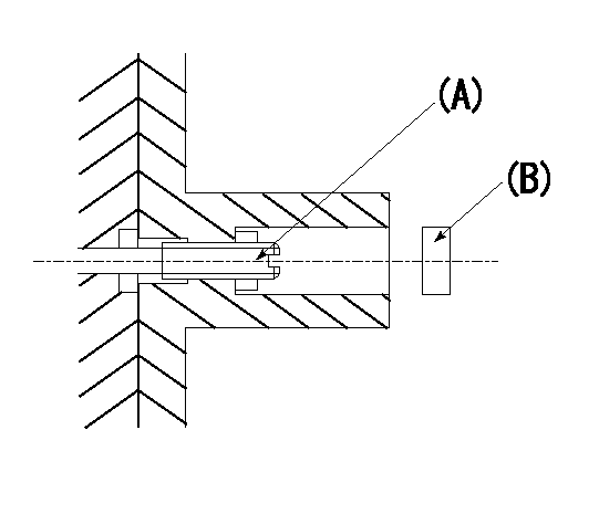
Tamper proof adjustment
(1)Set the full load screw at rack position Ra+0.4.
(2)Set the full load position Ra using screw (A).
----------
Ra=R1(10.8)mm
----------
----------
Ra=R1(10.8)mm
----------
Timing setting

(1)Pump vertical direction
(2)Position of timer's threaded hole at No 1 cylinder's beginning of injection
(3)B.T.D.C.: aa
(4)-
----------
aa=14deg
----------
a=(60deg)
----------
aa=14deg
----------
a=(60deg)
Have questions with 101603-4230?
Group cross 101603-4230 ZEXEL
Isuzu
101603-4230
1156018992
INJECTION-PUMP ASSEMBLY
6BD1
6BD1