Rating:
Information injection-pump assembly
BOSCH
9 400 612 944
9400612944
ZEXEL
101603-2730
1016032730
HINO
220205860A
220205860a
Service parts 101603-2730 INJECTION-PUMP ASSEMBLY:
1.
_
7.
COUPLING PLATE
8.
_
9.
_
11.
Nozzle and Holder
23600-2710A
12.
Open Pre:MPa(Kqf/cm2)
17.7{180}
15.
NOZZLE SET
Cross reference number
BOSCH
9 400 612 944
9400612944
ZEXEL
101603-2730
1016032730
HINO
220205860A
220205860a
Zexel num
Bosch num
Firm num
Name
101603-2730
9 400 612 944
220205860A HINO
INJECTION-PUMP ASSEMBLY
H07C-T K 14BF INJECTION PUMP ASSY PE6AD PE
H07C-T K 14BF INJECTION PUMP ASSY PE6AD PE
Calibration Data:
Adjustment conditions
Test oil
1404 Test oil ISO4113 or {SAEJ967d}
1404 Test oil ISO4113 or {SAEJ967d}
Test oil temperature
degC
40
40
45
Nozzle and nozzle holder
105780-8140
Bosch type code
EF8511/9A
Nozzle
105780-0000
Bosch type code
DN12SD12T
Nozzle holder
105780-2080
Bosch type code
EF8511/9
Opening pressure
MPa
17.2
Opening pressure
kgf/cm2
175
Injection pipe
Outer diameter - inner diameter - length (mm) mm 6-2-600
Outer diameter - inner diameter - length (mm) mm 6-2-600
Overflow valve
134424-0920
Overflow valve opening pressure
kPa
162
147
177
Overflow valve opening pressure
kgf/cm2
1.65
1.5
1.8
Tester oil delivery pressure
kPa
157
157
157
Tester oil delivery pressure
kgf/cm2
1.6
1.6
1.6
Direction of rotation (viewed from drive side)
Right R
Right R
Injection timing adjustment
Direction of rotation (viewed from drive side)
Right R
Right R
Injection order
1-4-2-6-
3-5
Pre-stroke
mm
4.8
4.77
4.83
Beginning of injection position
Drive side NO.1
Drive side NO.1
Difference between angles 1
Cal 1-4 deg. 60 59.75 60.25
Cal 1-4 deg. 60 59.75 60.25
Difference between angles 2
Cyl.1-2 deg. 120 119.75 120.25
Cyl.1-2 deg. 120 119.75 120.25
Difference between angles 3
Cal 1-6 deg. 180 179.75 180.25
Cal 1-6 deg. 180 179.75 180.25
Difference between angles 4
Cal 1-3 deg. 240 239.75 240.25
Cal 1-3 deg. 240 239.75 240.25
Difference between angles 5
Cal 1-5 deg. 300 299.75 300.25
Cal 1-5 deg. 300 299.75 300.25
Injection quantity adjustment
Adjusting point
A
Rack position
10.6
Pump speed
r/min
800
800
800
Average injection quantity
mm3/st.
108.5
107
110
Max. variation between cylinders
%
0
-3.5
3.5
Basic
*
Fixing the lever
*
Boost pressure
kPa
36
36
Boost pressure
mmHg
270
270
Injection quantity adjustment_02
Adjusting point
-
Rack position
7.2+-0.5
Pump speed
r/min
455
455
455
Average injection quantity
mm3/st.
10
9
11
Max. variation between cylinders
%
0
-10
10
Fixing the rack
*
Boost pressure
kPa
0
0
0
Boost pressure
mmHg
0
0
0
Remarks
Adjust only variation between cylinders; adjust governor according to governor specifications.
Adjust only variation between cylinders; adjust governor according to governor specifications.
Injection quantity adjustment_03
Adjusting point
E
Rack position
-
Pump speed
r/min
100
100
100
Average injection quantity
mm3/st.
130
130
140
Fixing the lever
*
Boost pressure
kPa
0
0
0
Boost pressure
mmHg
0
0
0
Rack limit
*
Boost compensator adjustment
Pump speed
r/min
800
800
800
Rack position
9.15
Boost pressure
kPa
5.3
4
6.6
Boost pressure
mmHg
40
30
50
Boost compensator adjustment_02
Pump speed
r/min
800
800
800
Rack position
10.6
Boost pressure
kPa
22.7
16
29.4
Boost pressure
mmHg
170
120
220
Timer adjustment
Pump speed
r/min
900--
Advance angle
deg.
0
0
0
Remarks
Start
Start
Timer adjustment_02
Pump speed
r/min
850
Advance angle
deg.
0.3
Timer adjustment_03
Pump speed
r/min
1000
Remarks
Measure the actual advance angle.
Measure the actual advance angle.
Timer adjustment_04
Pump speed
r/min
-
Advance angle
deg.
1.5
1.2
1.8
Remarks
Measure the actual speed, stop
Measure the actual speed, stop
Test data Ex:
Governor adjustment
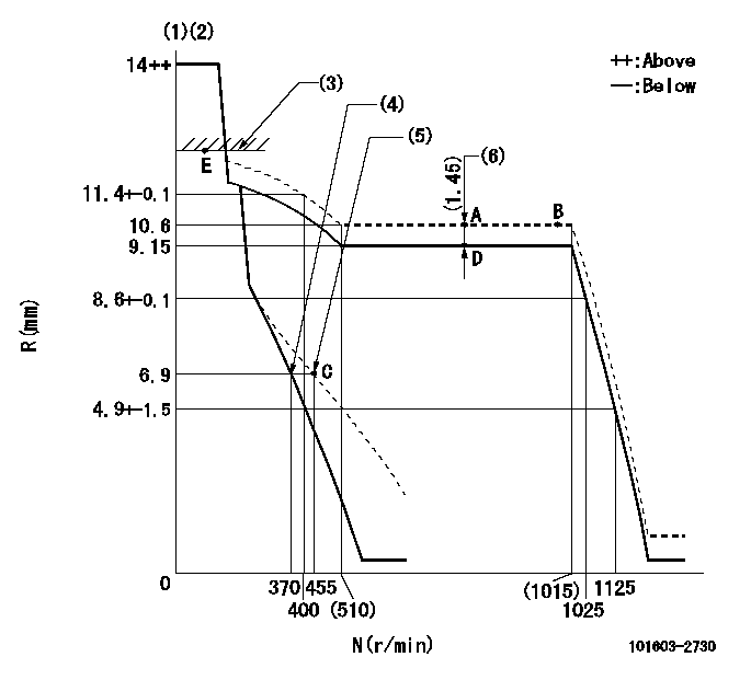
N:Pump speed
R:Rack position (mm)
(1)Notch fixed: K
(2)Tolerance for racks not indicated: +-0.05mm.
(3)RACK LIMIT
(4)Main spring setting
(5)Set idle sub-spring
(6)Boost compensator stroke
----------
K=7
----------
----------
K=7
----------
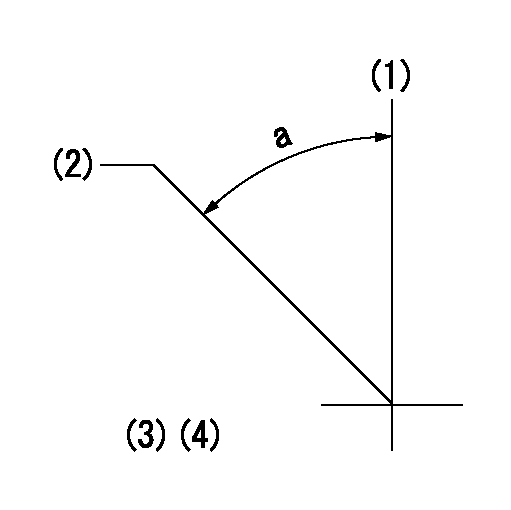
Speed control lever angle
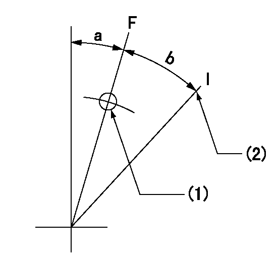
F:Full speed
I:Idle
(1)Use the hole at R = aa
(2)Stopper bolt setting
----------
aa=100mm
----------
a=(1deg)+-5deg b=(19deg)+-5deg
----------
aa=100mm
----------
a=(1deg)+-5deg b=(19deg)+-5deg
Stop lever angle
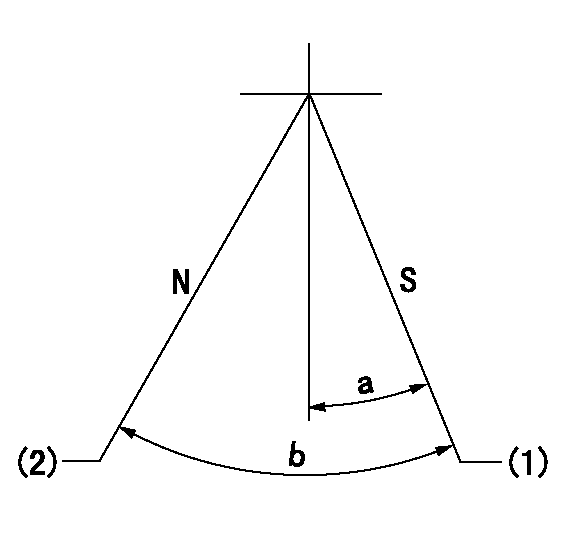
N:Pump normal
S:Stop the pump.
(1)Pump speed aa and rack position bb (to be sealed at delivery)
(2)Normal
----------
aa=0r/min bb=1-0.5mm
----------
a=21deg+-5deg b=(55deg)
----------
aa=0r/min bb=1-0.5mm
----------
a=21deg+-5deg b=(55deg)
0000001501 TAMPER PROOF
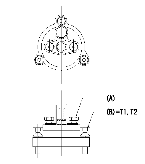
Tamperproofing-equipped boost compensator cover installation procedure
(A): After adjusting the boost compensator, assemble then tighten the bolts to remove the heads.
(B): Specified torque
(1)Before adjusting the governor and the boost compensator, tighten the screw to the specified torque.
(Tightening torque T = T1 maximum)
(2)After adjusting the governor and the boost compensator, tighten to the specified torque to break off the bolt heads.
(Tightening torque T = T2)
----------
T1=2.5N-m(0.25kgf-m) T2=2.9~4.4N-m(0.3~0.45kgf-m)
----------
----------
T1=2.5N-m(0.25kgf-m) T2=2.9~4.4N-m(0.3~0.45kgf-m)
----------
Timing setting
(1)Pump vertical direction
(2)Coupling's key groove position at No 1 cylinder's beginning of injection
(3)-
(4)-
----------
----------
a=(50deg)
----------
----------
a=(50deg)
Have questions with 101603-2730?
Group cross 101603-2730 ZEXEL
Hino
101603-2730
9 400 612 944
220205860A
INJECTION-PUMP ASSEMBLY
H07C-T
H07C-T