
Rating:
Information injection-pump assembly
BOSCH
9 400 611 256
9400611256
ZEXEL
101603-2650
1016032650
HINO
220205650A
220205650a
Service parts 101603-2650 INJECTION-PUMP ASSEMBLY:
1.
_
7.
COUPLING PLATE
8.
_
9.
_
11.
Nozzle and Holder
23600-2710A
12.
Open Pre:MPa(Kqf/cm2)
17.7{180}
15.
NOZZLE SET
Include in #1:
101603-2650
as INJECTION-PUMP ASSEMBLY
Include in #2:
104749-6930
as _
Cross reference number
BOSCH
9 400 611 256
9400611256
ZEXEL
101603-2650
1016032650
HINO
220205650A
220205650a
Zexel num
Bosch num
Firm num
Name
101603-2650
9 400 611 256
220205650A HINO
INJECTION-PUMP ASSEMBLY
H07C-T K 14BF INJECTION PUMP ASSY PE6AD PE
H07C-T K 14BF INJECTION PUMP ASSY PE6AD PE
Calibration Data:
Adjustment conditions
Test oil
1404 Test oil ISO4113 or {SAEJ967d}
1404 Test oil ISO4113 or {SAEJ967d}
Test oil temperature
degC
40
40
45
Nozzle and nozzle holder
105780-8140
Bosch type code
EF8511/9A
Nozzle
105780-0000
Bosch type code
DN12SD12T
Nozzle holder
105780-2080
Bosch type code
EF8511/9
Opening pressure
MPa
17.2
Opening pressure
kgf/cm2
175
Injection pipe
Outer diameter - inner diameter - length (mm) mm 6-2-600
Outer diameter - inner diameter - length (mm) mm 6-2-600
Overflow valve
134424-0920
Overflow valve opening pressure
kPa
162
147
177
Overflow valve opening pressure
kgf/cm2
1.65
1.5
1.8
Tester oil delivery pressure
kPa
157
157
157
Tester oil delivery pressure
kgf/cm2
1.6
1.6
1.6
Direction of rotation (viewed from drive side)
Right R
Right R
Injection timing adjustment
Direction of rotation (viewed from drive side)
Right R
Right R
Injection order
1-4-2-6-
3-5
Pre-stroke
mm
4.8
4.77
4.83
Beginning of injection position
Drive side NO.1
Drive side NO.1
Difference between angles 1
Cal 1-4 deg. 60 59.75 60.25
Cal 1-4 deg. 60 59.75 60.25
Difference between angles 2
Cyl.1-2 deg. 120 119.75 120.25
Cyl.1-2 deg. 120 119.75 120.25
Difference between angles 3
Cal 1-6 deg. 180 179.75 180.25
Cal 1-6 deg. 180 179.75 180.25
Difference between angles 4
Cal 1-3 deg. 240 239.75 240.25
Cal 1-3 deg. 240 239.75 240.25
Difference between angles 5
Cal 1-5 deg. 300 299.75 300.25
Cal 1-5 deg. 300 299.75 300.25
Injection quantity adjustment
Adjusting point
A
Rack position
10.6
Pump speed
r/min
1100
1100
1100
Average injection quantity
mm3/st.
106
104.5
107.5
Max. variation between cylinders
%
0
-3.5
3.5
Basic
*
Fixing the lever
*
Boost pressure
kPa
36
36
Boost pressure
mmHg
270
270
Injection quantity adjustment_02
Adjusting point
-
Rack position
7.2+-0.5
Pump speed
r/min
420
420
420
Average injection quantity
mm3/st.
10
9
11
Max. variation between cylinders
%
0
-10
10
Fixing the rack
*
Boost pressure
kPa
0
0
0
Boost pressure
mmHg
0
0
0
Remarks
Adjust only variation between cylinders; adjust governor according to governor specifications.
Adjust only variation between cylinders; adjust governor according to governor specifications.
Injection quantity adjustment_03
Adjusting point
E
Rack position
-
Pump speed
r/min
100
100
100
Average injection quantity
mm3/st.
135
135
145
Fixing the lever
*
Boost pressure
kPa
0
0
0
Boost pressure
mmHg
0
0
0
Rack limit
*
Boost compensator adjustment
Pump speed
r/min
800
800
800
Rack position
R1-1.45
Boost pressure
kPa
5.3
4
6.6
Boost pressure
mmHg
40
30
50
Boost compensator adjustment_02
Pump speed
r/min
800
800
800
Rack position
R1(10.6)
Boost pressure
kPa
22.7
16
29.4
Boost pressure
mmHg
170
120
220
Timer adjustment
Pump speed
r/min
900--
Advance angle
deg.
0
0
0
Remarks
Start
Start
Timer adjustment_02
Pump speed
r/min
850
Advance angle
deg.
0.3
Timer adjustment_03
Pump speed
r/min
1050
Advance angle
deg.
1.5
1.2
1.8
Remarks
Finish
Finish
Test data Ex:
Governor adjustment
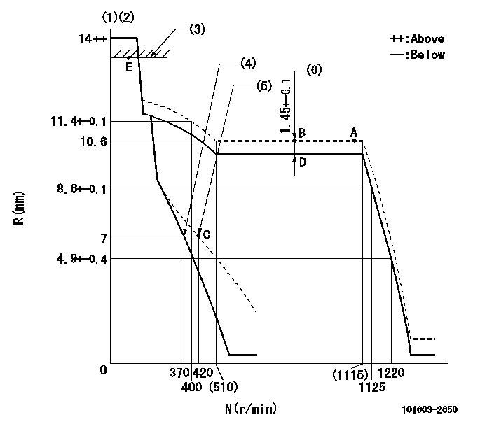
N:Pump speed
R:Rack position (mm)
(1)Target notch: K
(2)Tolerance for racks not indicated: +-0.05mm.
(3)RACK LIMIT
(4)Main spring setting
(5)Set idle sub-spring
(6)Boost compensator stroke
----------
K=7
----------
----------
K=7
----------
Speed control lever angle
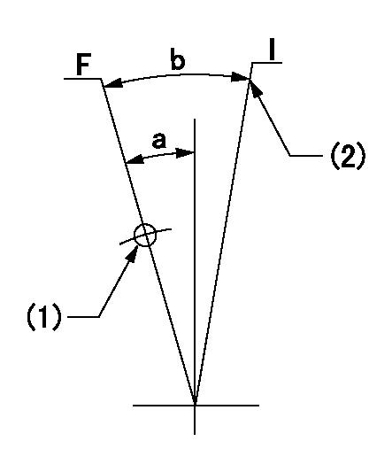
F:Full speed
I:Idle
(1)Use the hole at R = aa
(2)Stopper bolt setting
----------
aa=100mm
----------
a=4deg+-5deg b=22deg+-5deg
----------
aa=100mm
----------
a=4deg+-5deg b=22deg+-5deg
Stop lever angle
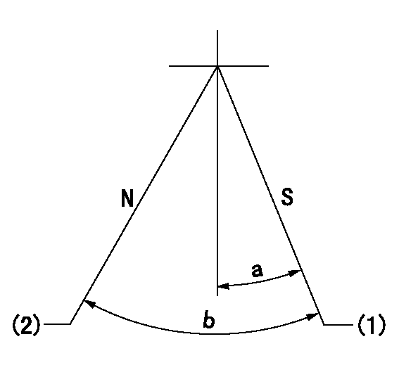
N:Pump normal
S:Stop the pump.
(1)Pump speed aa and rack position bb (to be sealed at delivery)
(2)Normal
----------
aa=0r/min bb=1-0.5mm
----------
a=21deg+-5deg b=(55deg)
----------
aa=0r/min bb=1-0.5mm
----------
a=21deg+-5deg b=(55deg)
0000001501 RACK SENSOR
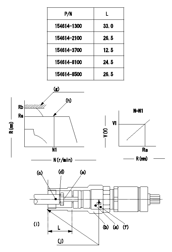
(g) rack limit
(h) rack sensor performance confirmation position
(i) pump end face
(j) Apply red paint.
Rack sensor adjustment (-5*20, threaded type, with A type rack limiter)
1. Rack limit adjustment
(1)When installing joint (b), select a shim (d) so that the rack limit rack position is Rb and the injection quantity is Qa.
(2)Install rod (E) to the rack (c).
(3)Select a joint (b) from the table above so that the distance from the pump end face to the rod (e) is L - 0.2 mm at rack position Rb.
2. Rack sensor adjustment
(1)Screw in the bobbin (A) until it contacts the joint (B).
(2)Fix the lever and set the pump speed at N1 and the rack position at Ra.
(3)Adjust the amount that the bobbin (a) is screwed in so that the amp's output voltage is V1. Then, fix using nut (f).
(4)Set the lever at the full speed side and confirm that the amp's output voltage is V1.
(5)Stick the caution plate on the top of the joint and apply red paint to the joint (b) and nut (f) join, and to the pump end face and joint (b) join.
Speed N1, Rack position = Ra, output voltage V1+-0.01 (V), rack sensor supply voltage 5+-0.01 (V)
----------
Qa=135+10mm3/st Ra=10.6mm N1=1100r/min V1=2.5+-0.01V
----------
----------
Qa=135+10mm3/st Ra=10.6mm N1=1100r/min V1=2.5+-0.01V
----------
Timing setting
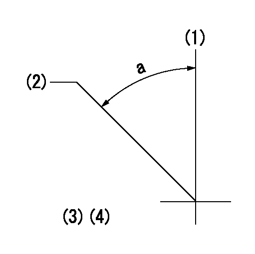
(1)Pump vertical direction
(2)Coupling's key groove position at No 1 cylinder's beginning of injection
(3)-
(4)-
----------
----------
a=(50deg)
----------
----------
a=(50deg)
Have questions with 101603-2650?
Group cross 101603-2650 ZEXEL
Hino
Hino
Hino
101603-2650
9 400 611 256
220205650A
INJECTION-PUMP ASSEMBLY
H07C-T
H07C-T