
Rating:
Information injection-pump assembly
ZEXEL
101603-0080
1016030080
ISUZU
1156015012
1156015012
Service parts 101603-0080 INJECTION-PUMP ASSEMBLY:
1.
_
7.
COUPLING PLATE
8.
_
9.
_
11.
Nozzle and Holder
12.
Open Pre:MPa(Kqf/cm2)
18.1(185)

15.
NOZZLE SET
Cross reference number
ZEXEL
101603-0080
1016030080
ISUZU
1156015012
1156015012
Zexel num
Bosch num
Firm num
Name
101603-0080
1156015012 ISUZU
INJECTION-PUMP ASSEMBLY
6BB1 * K
6BB1 * K
Calibration Data:
Adjustment conditions
Test oil
1404 Test oil ISO4113 or {SAEJ967d}
1404 Test oil ISO4113 or {SAEJ967d}
Test oil temperature
degC
40
40
45
Nozzle and nozzle holder
105780-8140
Bosch type code
EF8511/9A
Nozzle
105780-0000
Bosch type code
DN12SD12T
Nozzle holder
105780-2080
Bosch type code
EF8511/9
Opening pressure
MPa
17.2
Opening pressure
kgf/cm2
175
Injection pipe
Outer diameter - inner diameter - length (mm) mm 6-2-600
Outer diameter - inner diameter - length (mm) mm 6-2-600
Overflow valve
132424-0620
Overflow valve opening pressure
kPa
157
123
191
Overflow valve opening pressure
kgf/cm2
1.6
1.25
1.95
Tester oil delivery pressure
kPa
157
157
157
Tester oil delivery pressure
kgf/cm2
1.6
1.6
1.6
Direction of rotation (viewed from drive side)
Right R
Right R
Injection timing adjustment
Direction of rotation (viewed from drive side)
Right R
Right R
Injection order
1-5-3-6-
2-4
Pre-stroke
mm
3.6
3.55
3.65
Beginning of injection position
Drive side NO.1
Drive side NO.1
Difference between angles 1
Cal 1-5 deg. 60 59.5 60.5
Cal 1-5 deg. 60 59.5 60.5
Difference between angles 2
Cal 1-3 deg. 120 119.5 120.5
Cal 1-3 deg. 120 119.5 120.5
Difference between angles 3
Cal 1-6 deg. 180 179.5 180.5
Cal 1-6 deg. 180 179.5 180.5
Difference between angles 4
Cyl.1-2 deg. 240 239.5 240.5
Cyl.1-2 deg. 240 239.5 240.5
Difference between angles 5
Cal 1-4 deg. 300 299.5 300.5
Cal 1-4 deg. 300 299.5 300.5
Injection quantity adjustment
Adjusting point
-
Rack position
10.8
Pump speed
r/min
950
950
950
Average injection quantity
mm3/st.
61.4
59.8
63
Max. variation between cylinders
%
0
-2.5
2.5
Basic
*
Fixing the rack
*
Standard for adjustment of the maximum variation between cylinders
*
Injection quantity adjustment_02
Adjusting point
H
Rack position
9.5+-0.5
Pump speed
r/min
275
275
275
Average injection quantity
mm3/st.
7.4
6.1
8.7
Max. variation between cylinders
%
0
-14
14
Fixing the rack
*
Standard for adjustment of the maximum variation between cylinders
*
Injection quantity adjustment_03
Adjusting point
A
Rack position
R1(10.8)
Pump speed
r/min
950
950
950
Average injection quantity
mm3/st.
61.4
60.4
62.4
Basic
*
Fixing the lever
*
Injection quantity adjustment_04
Adjusting point
B
Rack position
R1+0.2
Pump speed
r/min
1600
1600
1600
Average injection quantity
mm3/st.
71
69.4
72.6
Fixing the lever
*
Injection quantity adjustment_05
Adjusting point
C
Rack position
R1-0.05
Pump speed
r/min
1300
1300
1300
Average injection quantity
mm3/st.
66
64.4
67.6
Fixing the lever
*
Injection quantity adjustment_06
Adjusting point
D
Rack position
R1-0.2
Pump speed
r/min
650
650
650
Average injection quantity
mm3/st.
45.7
44.1
47.3
Fixing the lever
*
Injection quantity adjustment_07
Adjusting point
I
Rack position
13.6+-0.
5
Pump speed
r/min
150
150
150
Average injection quantity
mm3/st.
87
87
95
Fixing the lever
*
Rack limit
*
Timer adjustment
Pump speed
r/min
1400--
Advance angle
deg.
0
0
0
Remarks
Start
Start
Timer adjustment_02
Pump speed
r/min
1350
Advance angle
deg.
0.5
Timer adjustment_03
Pump speed
r/min
1400
Advance angle
deg.
1.3
Timer adjustment_04
Pump speed
r/min
1500
Advance angle
deg.
2.3
1.8
2.8
Timer adjustment_05
Pump speed
r/min
1600
Advance angle
deg.
4
3.5
4.5
Remarks
Finish
Finish
Test data Ex:
Governor adjustment
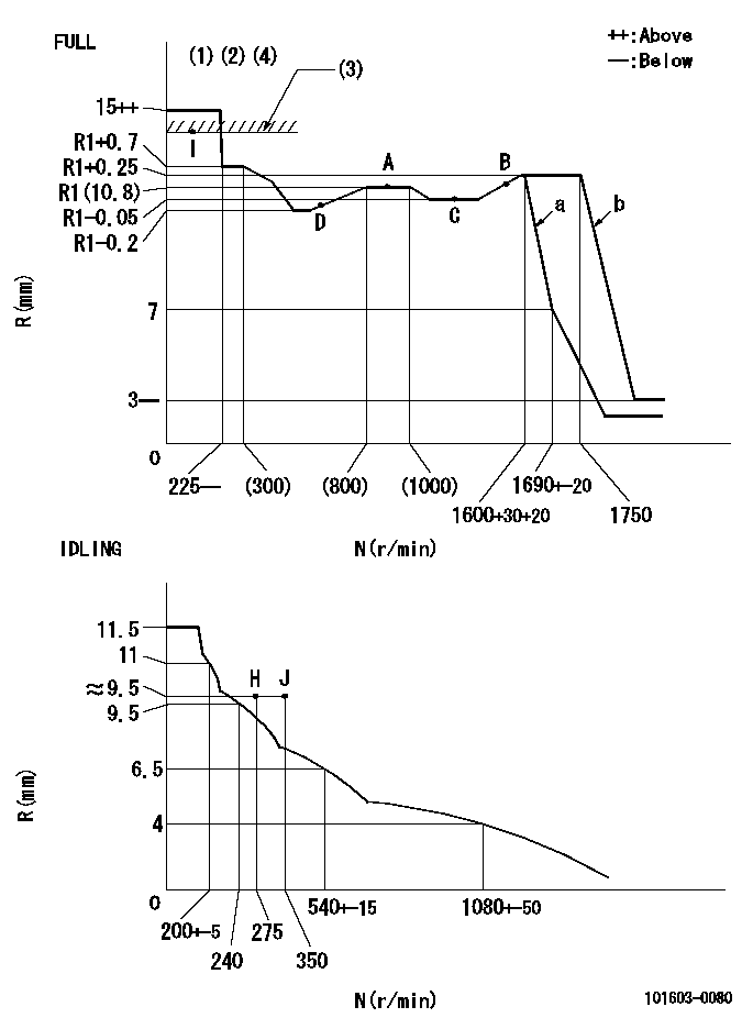
N:Pump speed
R:Rack position (mm)
(1)Torque cam stamping: T1
(2)Torque control stroke: L2
(3)RACK LIMIT
(4)Perform speed droop adjustment using the torque control spring in accordance with specification 'a' and confirm specification 'b.' Set the final full speed position lever in accordance with specification 'a.'
----------
T1=27 L2=(1.1)+-0.05mm
----------
----------
T1=27 L2=(1.1)+-0.05mm
----------
Speed control lever angle
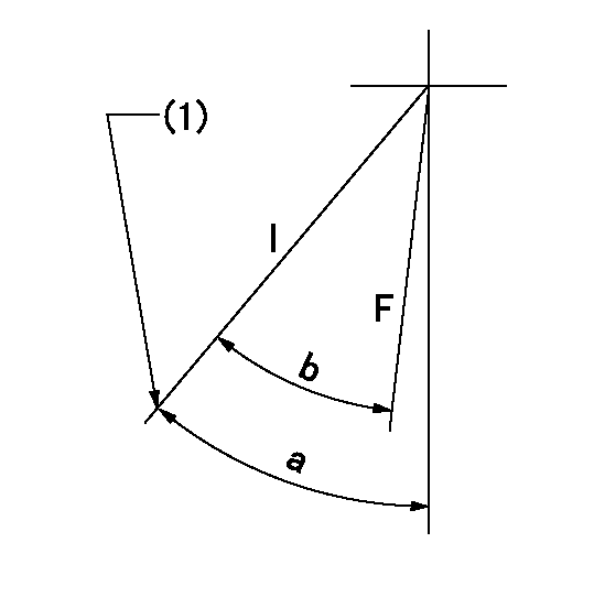
F:Full speed
I:Idle
(1)Stopper bolt set position 'H'
----------
----------
a=42deg+-5deg b=37deg+-3deg
----------
----------
a=42deg+-5deg b=37deg+-3deg
Stop lever angle
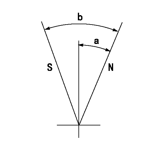
N:Pump normal
S:Stop the pump.
----------
----------
a=25deg+-5deg b=40deg+-5deg
----------
----------
a=25deg+-5deg b=40deg+-5deg
0000001501 VARIABLE TORQUE CONTROL
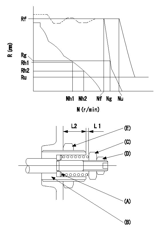
N:Pump speed (r/min)
R:Rack position (mm)
Adjusting shim A
Guide screw B
(c) Nut
(d) Nut
(e) nut
Torque control spring adjustment method for model responding to speed droop
[Advice]
Confirm that adjusting shim (A) thickness t = 1.3~1.5 mm is assembled before beginning adjustment.
(1)Temporary idle lever position setting
1. Refer to the RLD type governor service manual (Publication no. EE13E-11083).
(2)Idling spring adjustment
1. Refer to the RLD type governor service manual (Publication no. EE13E-11083).
(3)Governor spring setting adjustment
1. Temporarily fix so that the governor shaft's guide screw B protrudes L2 (18 mm) from the end of the governor.
2. Set the control lever where it contacts the idle stopper bolt.
3. Increase the speed to Nh2+100 r/min or more.
4. Adjust using the two nuts C and D so that L1 = 0.3+0.5 mm and fix temporarily.
5. Adjust the protrusion L2 of the guide screw (B) so that the rack position at Nh1 is Rh1 and at Nh2 is Rh2. Then fix using the nut (E).
6. Further increase the speed and readjust the two nuts (C) and (D) so that there is no change in L1 until Nf+50 r/min. Then fix temporarily.
[Advice]
When L1 becomes smaller while speed is increasing to Nf+50 r/min, decrease speed by Nh2+100 r/min.
Adjust so that L1 is even smaller, then again increase speed to Nf+50 r/min and confirm that L1 does not change.
(4)Full load position setting
1. Refer to the RLD type governor service manual (Publication no. EE13E-11083).
(5)Torque control spring adjustment
1. Set the control lever so that it contacts the full speed stopper bolt.
2. At the specified speed Nf, adjust using the full speed stopper bolt so that governing begins, then fix temporarily.
3. Increase the speed and adjust using the two nuts (C) and (D) so that the rack position Rg can be obtained at the specified speed Ng. Fix temporarily.
4. Decrease the speed and confirm the governing point (the beginning of governing point) at the specified speed Nf.
5. Set the speed at Nf-50 r/min.
6. Measure the torque control stroke (L1) and adjust to the specified stroke (L1) using the shim (A).
7. After completing shim adjustment, repeat the above adjustment using the two nuts.
8. After confirming the specifications Nf and Ng, fix the two nuts (C) and (D).
9. In this condition, increase the speed and confirm that R = 0 can be obtained.
(6)Full speed lever position setting
1. Set the control lever so that it contacts the full speed stopper bolt.
2. At the specified speed Nu, adjust using the full speed stopper bolt so that governing begins, then fix temporarily
3. Increase the speed and confirm that the specified rack position Ru can be obtained.
4. Adjust using the full speed stopper bolt so that governing begins at the specified speed Nf, then fix.
5. Confirm that the result is the same as that in '(5) Torque control spring adjustment.'
6. Confirm that the control lever operating angle is within the specifications.
(7)Rack limit adjustment
1. Refer to the RLD type governor service manual (Publication no. EE13E-11083).
----------
----------
----------
----------
Timing setting

(1)Pump vertical direction
(2)Position of timer's threaded hole at No 1 cylinder's beginning of injection
(3)B.T.D.C.: aa
(4)-
----------
aa=14deg
----------
a=(60deg)
----------
aa=14deg
----------
a=(60deg)
Have questions with 101603-0080?
Group cross 101603-0080 ZEXEL
Isuzu
101603-0080
1156015012
INJECTION-PUMP ASSEMBLY
6BB1
6BB1