Rating:
Information injection-pump assembly
BOSCH
9 400 614 861
9400614861
ZEXEL
101602-4951
1016024951
ISUZU
1156022220
1156022220
Service parts 101602-4951 INJECTION-PUMP ASSEMBLY:
1.
_

5.
AUTOM. ADVANCE MECHANIS
8.
_
9.
_
11.
Nozzle and Holder
1-15300-104-2
12.
Open Pre:MPa(Kqf/cm2)
18.1(185)

15.
NOZZLE SET
Include in #1:
101602-4951
as INJECTION-PUMP ASSEMBLY
Include in #2:
104740-1023
as _
Cross reference number
BOSCH
9 400 614 861
9400614861
ZEXEL
101602-4951
1016024951
ISUZU
1156022220
1156022220
Zexel num
Bosch num
Firm num
Name
101602-4951
9 400 614 861
1156022220 ISUZU
INJECTION-PUMP ASSEMBLY
6BG1T * K 14BF PE6AD PE
6BG1T * K 14BF PE6AD PE
Calibration Data:
Adjustment conditions
Test oil
1404 Test oil ISO4113 or {SAEJ967d}
1404 Test oil ISO4113 or {SAEJ967d}
Test oil temperature
degC
40
40
45
Nozzle and nozzle holder
105780-8140
Bosch type code
EF8511/9A
Nozzle
105780-0000
Bosch type code
DN12SD12T
Nozzle holder
105780-2080
Bosch type code
EF8511/9
Opening pressure
MPa
17.2
Opening pressure
kgf/cm2
175
Injection pipe
Outer diameter - inner diameter - length (mm) mm 6-2-600
Outer diameter - inner diameter - length (mm) mm 6-2-600
Overflow valve opening pressure
kPa
157
123
191
Overflow valve opening pressure
kgf/cm2
1.6
1.25
1.95
Tester oil delivery pressure
kPa
157
157
157
Tester oil delivery pressure
kgf/cm2
1.6
1.6
1.6
Direction of rotation (viewed from drive side)
Right R
Right R
Injection timing adjustment
Direction of rotation (viewed from drive side)
Right R
Right R
Injection order
1-5-3-6-
2-4
Pre-stroke
mm
3.6
3.55
3.65
Beginning of injection position
Drive side NO.1
Drive side NO.1
Difference between angles 1
Cal 1-5 deg. 60 59.5 60.5
Cal 1-5 deg. 60 59.5 60.5
Difference between angles 2
Cal 1-3 deg. 120 119.5 120.5
Cal 1-3 deg. 120 119.5 120.5
Difference between angles 3
Cal 1-6 deg. 180 179.5 180.5
Cal 1-6 deg. 180 179.5 180.5
Difference between angles 4
Cyl.1-2 deg. 240 239.5 240.5
Cyl.1-2 deg. 240 239.5 240.5
Difference between angles 5
Cal 1-4 deg. 300 299.5 300.5
Cal 1-4 deg. 300 299.5 300.5
Injection quantity adjustment
Adjusting point
A
Rack position
10
Pump speed
r/min
1200
1200
1200
Average injection quantity
mm3/st.
83.5
82
85
Max. variation between cylinders
%
0
-2.5
2.5
Basic
*
Fixing the lever
*
Injection quantity adjustment_02
Adjusting point
B
Rack position
6.4+-0.5
Pump speed
r/min
375
375
375
Average injection quantity
mm3/st.
9
7.5
10.5
Max. variation between cylinders
%
0
-14
14
Fixing the rack
*
Test data Ex:
Governor adjustment
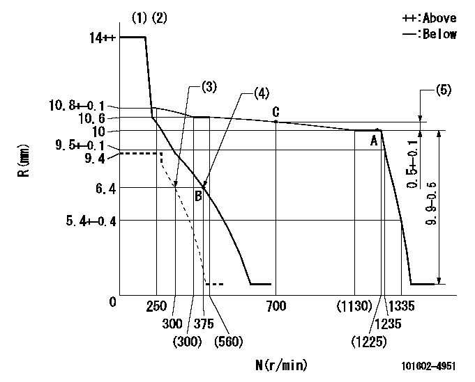
N:Pump speed
R:Rack position (mm)
(1)Target notch: K
(2)Tolerance for racks not indicated: +-0.05mm.
(3)Set idle sub-spring
(4)Main spring setting
(5)Rack difference from N = N1
----------
K=15 N1=1175r/min
----------
----------
K=15 N1=1175r/min
----------
Speed control lever angle
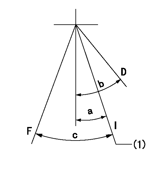
F:Full speed
I:Idle
D:Dead point
(1)Stopper bolt setting
----------
----------
a=18deg+-1deg b=(20deg)+-3deg c=23deg+-5deg
----------
----------
a=18deg+-1deg b=(20deg)+-3deg c=23deg+-5deg
Stop lever angle
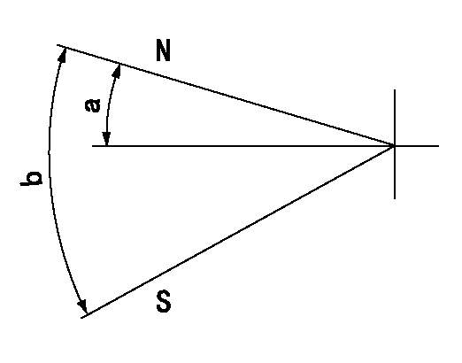
N:Pump normal
S:Stop the pump.
----------
----------
a=12deg+-5deg b=46deg+-5deg
----------
----------
a=12deg+-5deg b=46deg+-5deg
0000001501 LEVER
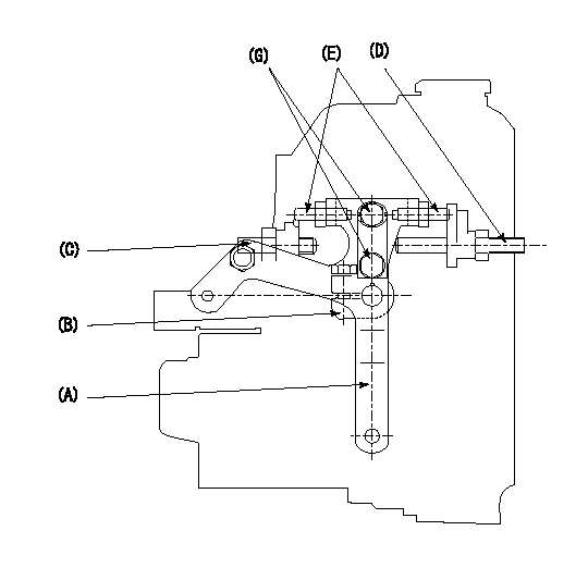
1. Variable lever adjustment
(1)Fix lever (B) in the idle position using bolts (C) and (D).
(2)Temporarily fix the lever (A) in the center of the elongated hole.
(3)Set the dead point position temporarily and measure the lever angle.
(4)Fix the lever (A) at the idle lever angle position using the bolt (E).
(5)Lock using bolt (G).
(6)After completing idle adjustment, loosen the full side stopper bolt (D).
(7)Move the lever (A) in the full speed direction.
(8)Fix bolt (D) at full speed position.
(9)Finally, measure the lever angle and set the idle stopper bolt (C) stop position.
----------
----------
----------
----------
Timing setting
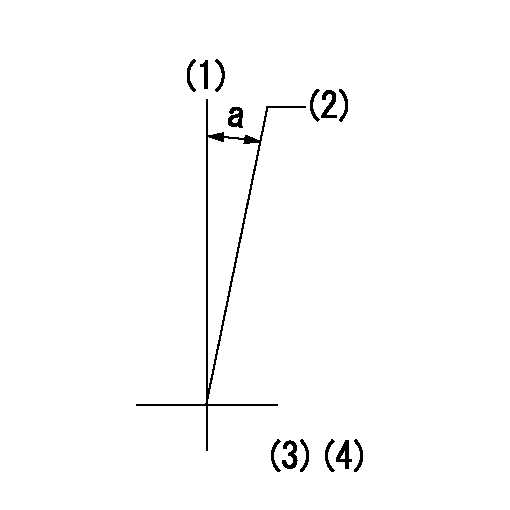
(1)Pump vertical direction
(2)Position of flywheel's threaded hole at No 1 cylinder's beginning of injection
(3)B.T.D.C.: aa
(4)-
----------
aa=13deg
----------
a=(10deg)
----------
aa=13deg
----------
a=(10deg)
Have questions with 101602-4951?
Group cross 101602-4951 ZEXEL
Isuzu
101602-4951
9 400 614 861
1156022220
INJECTION-PUMP ASSEMBLY
6BG1T
6BG1T