
Rating:
Information injection-pump assembly
ZEXEL
101601-9410
1016019410
Cross reference number
ZEXEL
101601-9410
1016019410
Zexel num
Bosch num
Firm num
Name
Calibration Data:
Adjustment conditions
Test oil
1404 Test oil ISO4113 or {SAEJ967d}
1404 Test oil ISO4113 or {SAEJ967d}
Test oil temperature
degC
40
40
45
Nozzle and nozzle holder
105780-8140
Bosch type code
EF8511/9A
Nozzle
105780-0000
Bosch type code
DN12SD12T
Nozzle holder
105780-2080
Bosch type code
EF8511/9
Opening pressure
MPa
17.2
Opening pressure
kgf/cm2
175
Injection pipe
Outer diameter - inner diameter - length (mm) mm 6-2-600
Outer diameter - inner diameter - length (mm) mm 6-2-600
Overflow valve opening pressure
kPa
157
123
191
Overflow valve opening pressure
kgf/cm2
1.6
1.25
1.95
Tester oil delivery pressure
kPa
157
157
157
Tester oil delivery pressure
kgf/cm2
1.6
1.6
1.6
Direction of rotation (viewed from drive side)
Right R
Right R
Injection timing adjustment
Direction of rotation (viewed from drive side)
Right R
Right R
Injection order
1-4-2-6-
3-5
Pre-stroke
mm
3
2.95
3.05
Beginning of injection position
Drive side NO.1
Drive side NO.1
Difference between angles 1
Cal 1-4 deg. 60 59.5 60.5
Cal 1-4 deg. 60 59.5 60.5
Difference between angles 2
Cyl.1-2 deg. 120 119.5 120.5
Cyl.1-2 deg. 120 119.5 120.5
Difference between angles 3
Cal 1-6 deg. 180 179.5 180.5
Cal 1-6 deg. 180 179.5 180.5
Difference between angles 4
Cal 1-3 deg. 240 239.5 240.5
Cal 1-3 deg. 240 239.5 240.5
Difference between angles 5
Cal 1-5 deg. 300 299.5 300.5
Cal 1-5 deg. 300 299.5 300.5
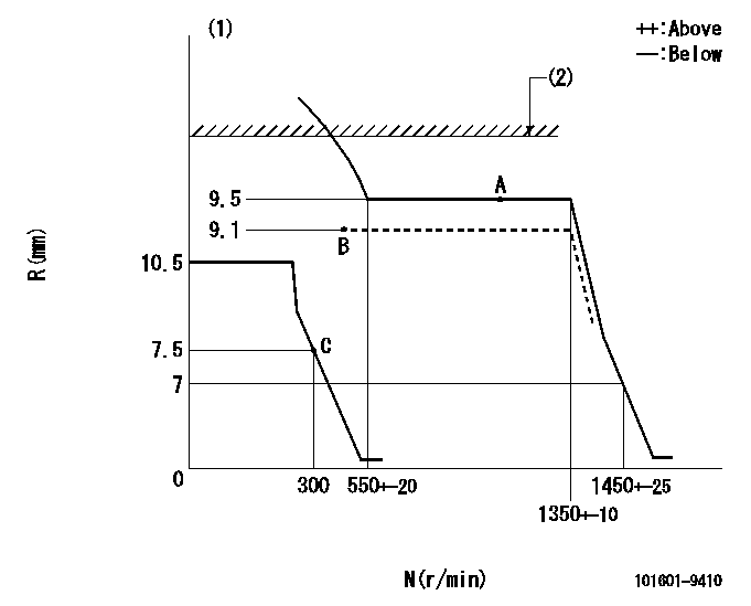
Injection quantity adjustment
Adjusting point
A
Rack position
9.5
Pump speed
r/min
750
750
750
Average injection quantity
mm3/st.
63
61.4
64.6
Max. variation between cylinders
%
0
-3.5
3.5
Basic
*
Fixing the lever
*
Boost pressure
kPa
50
50
Boost pressure
mmHg
375
375
Injection quantity adjustment_02
Adjusting point
B
Rack position
9.1
Pump speed
r/min
500
500
500
Average injection quantity
mm3/st.
44.2
42.6
45.8
Max. variation between cylinders
%
0
-5
5
Fixing the lever
*
Boost pressure
kPa
0
0
0
Boost pressure
mmHg
0
0
0
Injection quantity adjustment_03
Adjusting point
C
Rack position
7.8+-0.5
Pump speed
r/min
300
300
300
Average injection quantity
mm3/st.
9.5
7.7
11.3
Max. variation between cylinders
%
0
-10
10
Fixing the rack
*
Boost pressure
kPa
0
0
0
Boost pressure
mmHg
0
0
0
Remarks
Adjust only variation between cylinders; adjust governor according to governor specifications.
Adjust only variation between cylinders; adjust governor according to governor specifications.
Boost compensator adjustment
Pump speed
r/min
600
600
600
Rack position
9.1
Boost pressure
kPa
16
14.7
17.3
Boost pressure
mmHg
120
110
130
Boost compensator adjustment_02
Pump speed
r/min
600
600
600
Rack position
9.5
Boost pressure
kPa
36.7
30
43.4
Boost pressure
mmHg
275
225
325
Timer adjustment
Pump speed
r/min
300
Advance angle
deg.
1
0.5
1.5
Timer adjustment_02
Pump speed
r/min
600-150
Advance angle
deg.
0
0
0
Timer adjustment_03
Pump speed
r/min
1250+-50
Advance angle
deg.
0
0
0
Remarks
Beginning of advance.
Beginning of advance.
Timer adjustment_04
Pump speed
r/min
1350
Advance angle
deg.
1
0.5
1.5
Timer adjustment_05
Pump speed
r/min
-
Advance angle
deg.
2.5
2.5
2.5
Remarks
Measure the actual speed, stop
Measure the actual speed, stop
Test data Ex:
Governor adjustment
N:Pump speed
R:Rack position (mm)
(1)Target notch: K
(2)Rack limit using excess fuel lever: L1
----------
K=12 L1=10+0.2mm
----------
----------
K=12 L1=10+0.2mm
----------
Speed control lever angle
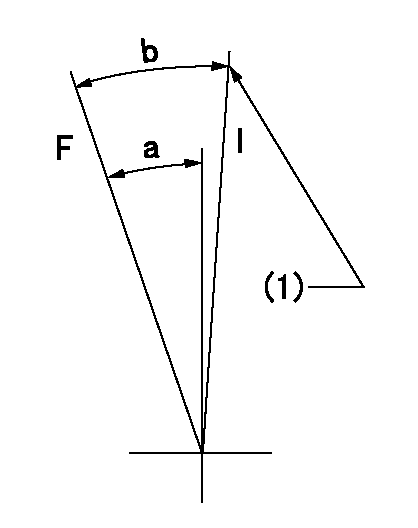
F:Full speed
I:Idle
(1)Stopper bolt setting
----------
----------
a=19deg+-3deg b=26deg+-5deg
----------
----------
a=19deg+-3deg b=26deg+-5deg
Stop lever angle
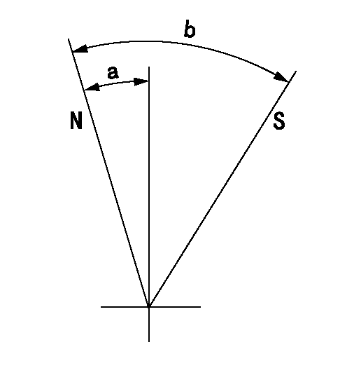
N:Pump normal
S:Stop the pump.
----------
----------
a=10.5deg+-5deg b=53deg+-5deg
----------
----------
a=10.5deg+-5deg b=53deg+-5deg
0000001501 GOV FULL LOAD ADJUSTMENT
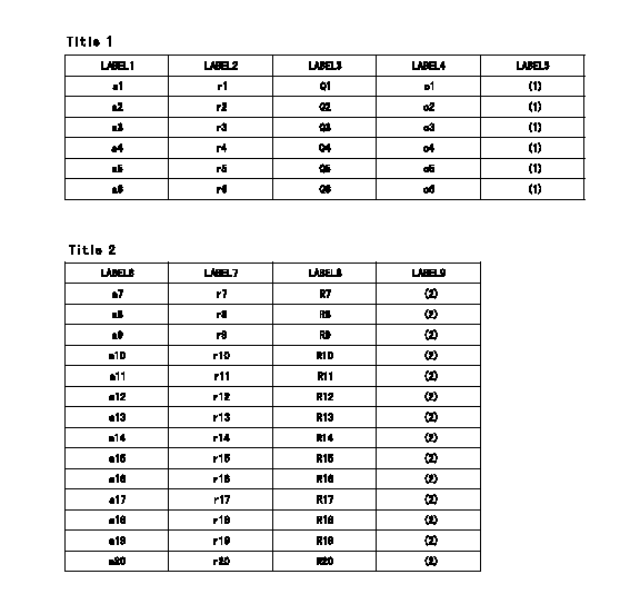
Title1:Full load stopper adjustment
Title2:Governor set speed
LABEL1:Distinguishing
LABEL2:Pump speed (r/min)
LABEL3:Ave. injection quantity (mm3/st)
LABEL4:Max. var. bet. cyl.
LABEL5:Remarks
LABEL6:Distinguishing
LABEL7:Governor set speed (r/min)
LABEL8:Maximum no-load speed (r/min)
LABEL9:Remarks
(1)Adjustment conditions are the same as those for measuring injection quantity.
(2)At high idle rack position L
----------
L=7mm
----------
a1=A a2=B a3=- a4=- a5=- a6=- r1=900r/min r2=750r/min r3=- r4=- r5=- r6=- Q1=73.2+-1.6mm3/st Q2=63+-1.6mm3/st Q3=- Q4=- Q5=- Q6=- c1=+-3.5% c2=+-3.5% c3=- c4=- c5=- c6=- a7=27 a8=26 a9=25 a10=24 a11=23 a12=22 a13=21 a14=20 a15=19 a16=18 a17=17 a18=16 a19=15 a20=- r7=1350r/min r8=1300r/min r9=1250r/min r10=1200r/min r11=1150r/min r12=1100r/min r13=1050r/min r14=1000r/min r15=950r/min r16=900r/min r17=850r/min r18=800r/min r19=750r/min r20=- R7=1450+-33r/min R8=1395+-32r/min R9=1340+-31r/min R10=1290+-30r/min R11=1235+-28r/min R12=1180+-27r/min R13=1130+-26r/min R14=1075+-25r/min R15=1020+-23r/min R16=965+-22r/min R17=915+-22r/min R18=860+-20r/min R19=805+-18r/min R20=-
----------
L=7mm
----------
a1=A a2=B a3=- a4=- a5=- a6=- r1=900r/min r2=750r/min r3=- r4=- r5=- r6=- Q1=73.2+-1.6mm3/st Q2=63+-1.6mm3/st Q3=- Q4=- Q5=- Q6=- c1=+-3.5% c2=+-3.5% c3=- c4=- c5=- c6=- a7=27 a8=26 a9=25 a10=24 a11=23 a12=22 a13=21 a14=20 a15=19 a16=18 a17=17 a18=16 a19=15 a20=- r7=1350r/min r8=1300r/min r9=1250r/min r10=1200r/min r11=1150r/min r12=1100r/min r13=1050r/min r14=1000r/min r15=950r/min r16=900r/min r17=850r/min r18=800r/min r19=750r/min r20=- R7=1450+-33r/min R8=1395+-32r/min R9=1340+-31r/min R10=1290+-30r/min R11=1235+-28r/min R12=1180+-27r/min R13=1130+-26r/min R14=1075+-25r/min R15=1020+-23r/min R16=965+-22r/min R17=915+-22r/min R18=860+-20r/min R19=805+-18r/min R20=-
Timing setting
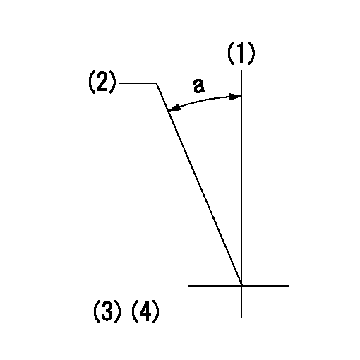
(1)Pump vertical direction
(2)Coupling's key groove position at No 1 cylinder's beginning of injection
(3)-
(4)-
----------
----------
a=(30deg)
----------
----------
a=(30deg)