
Rating:
Information injection-pump assembly
ZEXEL
101601-8132
1016018132
ISUZU
1156013382
1156013382
Cross reference number
ZEXEL
101601-8132
1016018132
ISUZU
1156013382
1156013382
Zexel num
Bosch num
Firm num
Name
Calibration Data:
Adjustment conditions
Test oil
1404 Test oil ISO4113 or {SAEJ967d}
1404 Test oil ISO4113 or {SAEJ967d}
Test oil temperature
degC
40
40
45
Nozzle and nozzle holder
105780-8140
Bosch type code
EF8511/9A
Nozzle
105780-0000
Bosch type code
DN12SD12T
Nozzle holder
105780-2080
Bosch type code
EF8511/9
Opening pressure
MPa
17.2
Opening pressure
kgf/cm2
175
Injection pipe
Outer diameter - inner diameter - length (mm) mm 6-2-600
Outer diameter - inner diameter - length (mm) mm 6-2-600
Overflow valve
132424-0620
Overflow valve opening pressure
kPa
157
123
191
Overflow valve opening pressure
kgf/cm2
1.6
1.25
1.95
Tester oil delivery pressure
kPa
157
157
157
Tester oil delivery pressure
kgf/cm2
1.6
1.6
1.6
Direction of rotation (viewed from drive side)
Right R
Right R
Injection timing adjustment
Direction of rotation (viewed from drive side)
Right R
Right R
Injection order
1-5-3-6-
2-4
Pre-stroke
mm
3.6
3.55
3.65
Beginning of injection position
Drive side NO.1
Drive side NO.1
Difference between angles 1
Cal 1-5 deg. 60 59.5 60.5
Cal 1-5 deg. 60 59.5 60.5
Difference between angles 2
Cal 1-3 deg. 120 119.5 120.5
Cal 1-3 deg. 120 119.5 120.5
Difference between angles 3
Cal 1-6 deg. 180 179.5 180.5
Cal 1-6 deg. 180 179.5 180.5
Difference between angles 4
Cyl.1-2 deg. 240 239.5 240.5
Cyl.1-2 deg. 240 239.5 240.5
Difference between angles 5
Cal 1-4 deg. 300 299.5 300.5
Cal 1-4 deg. 300 299.5 300.5
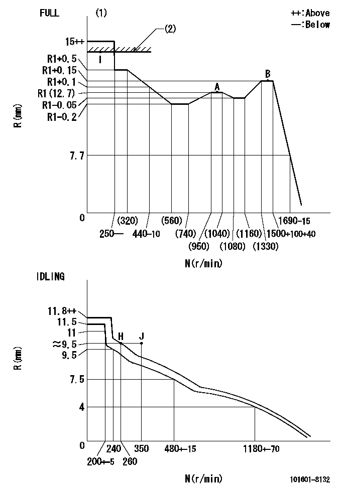
Injection quantity adjustment
Adjusting point
-
Rack position
12.7
Pump speed
r/min
1000
1000
1000
Average injection quantity
mm3/st.
78
76.4
79.6
Max. variation between cylinders
%
0
-2.5
2.5
Basic
*
Fixing the rack
*
Standard for adjustment of the maximum variation between cylinders
*
Injection quantity adjustment_02
Adjusting point
H
Rack position
9.5+-0.5
Pump speed
r/min
260
260
260
Average injection quantity
mm3/st.
8.1
6.8
9.4
Max. variation between cylinders
%
0
-14
14
Fixing the rack
*
Standard for adjustment of the maximum variation between cylinders
*
Injection quantity adjustment_03
Adjusting point
A
Rack position
R1(12.7)
Pump speed
r/min
1000
1000
1000
Average injection quantity
mm3/st.
78
77
79
Basic
*
Fixing the lever
*
Injection quantity adjustment_04
Adjusting point
I
Rack position
15+-0.5
Pump speed
r/min
150
150
150
Average injection quantity
mm3/st.
92
92
100
Fixing the lever
*
Rack limit
*
Timer adjustment
Pump speed
r/min
1350--
Advance angle
deg.
0
0
0
Remarks
Start
Start
Timer adjustment_02
Pump speed
r/min
1300
Advance angle
deg.
0.5
Timer adjustment_03
Pump speed
r/min
1400
Advance angle
deg.
2
1.5
2.5
Timer adjustment_04
Pump speed
r/min
1500
Advance angle
deg.
4.5
4
5
Remarks
Finish
Finish
Test data Ex:
Governor adjustment
N:Pump speed
R:Rack position (mm)
(1)Torque cam stamping: T1
(2)RACK LIMIT
----------
T1=78
----------
----------
T1=78
----------
Speed control lever angle
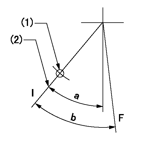
F:Full speed
I:Idle
(1)Use the hole at R = aa
(2)Stopper bolt set position 'H'
----------
aa=35mm
----------
a=42deg+-5deg b=(45deg)+-3deg
----------
aa=35mm
----------
a=42deg+-5deg b=(45deg)+-3deg
Stop lever angle
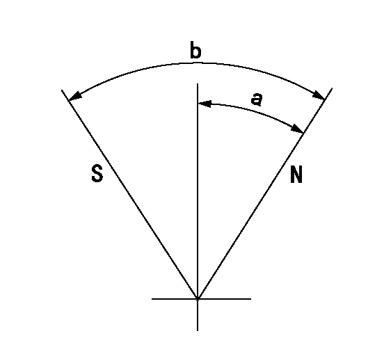
N:Pump normal
S:Stop the pump.
----------
----------
a=25deg+-5deg b=40deg+-5deg
----------
----------
a=25deg+-5deg b=40deg+-5deg
0000001501 RACK SENSOR
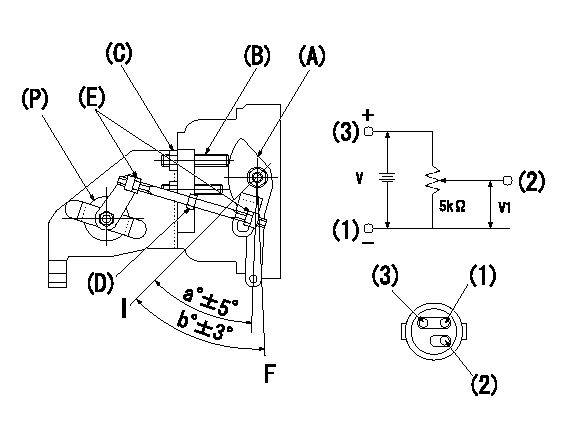
V1:Output voltage
Vf:Full side output voltage
F:Full-speed
I:Idle
(a) Speed lever
(B) Full side stopper bolt
(c) Nut
(d) Nut
(e) nut
(P) Potentiometer
1. Load sensor adjustment
(1)Apply voltage V to between the potentiometer (P)'s connector terminals (1) ~ (3) and measure the output voltage between (1) ~ (2).
(2)Move the speed lever (A) until it contacts the full side stopper bolt (B) and then turn the nut (D) to adjust the potentiometer (P)'s output voltage to Vf.
(3)Confirm that the speed lever (A) turns smoothly between idle and Full side, then fix using nut (E). (Tightening torque: 4.4~7N.m{0.5~0.7kgf.m})
(4)Move the speed lever (A) several times to contact full side stopper bolt (B) and confirm that the potentiometer (P) output voltage is Vf.
(5)Confirm that the speed lever (A) turns smoothly between idle and Full (b deg).
----------
V=DC24V Vf=16+-0.1V
----------
----------
V=DC24V Vf=16+-0.1V
----------
Timing setting

(1)Pump vertical direction
(2)Position of timer's threaded hole at No 1 cylinder's beginning of injection
(3)-
(4)-
----------
----------
a=(60deg)
----------
----------
a=(60deg)