Rating:
Information injection-pump assembly
BOSCH
9 400 619 718
9400619718
ZEXEL
101601-8110
1016018110
ISUZU
1156014172
1156014172
Service parts 101601-8110 INJECTION-PUMP ASSEMBLY:
1.
_
7.
COUPLING PLATE
8.
_
9.
_
11.
Nozzle and Holder
1-15300-084-0
12.
Open Pre:MPa(Kqf/cm2)
22.1{225}
15.
NOZZLE SET
Cross reference number
BOSCH
9 400 619 718
9400619718
ZEXEL
101601-8110
1016018110
ISUZU
1156014172
1156014172
Zexel num
Bosch num
Firm num
Name
101601-8110
9 400 619 718
1156014172 ISUZU
INJECTION-PUMP ASSEMBLY
6QA1 * K 14BF PE6AD PE
6QA1 * K 14BF PE6AD PE
Calibration Data:
Adjustment conditions
Test oil
1404 Test oil ISO4113 or {SAEJ967d}
1404 Test oil ISO4113 or {SAEJ967d}
Test oil temperature
degC
40
40
45
Nozzle and nozzle holder
105780-8140
Bosch type code
EF8511/9A
Nozzle
105780-0000
Bosch type code
DN12SD12T
Nozzle holder
105780-2080
Bosch type code
EF8511/9
Opening pressure
MPa
17.2
Opening pressure
kgf/cm2
175
Injection pipe
Outer diameter - inner diameter - length (mm) mm 6-2-600
Outer diameter - inner diameter - length (mm) mm 6-2-600
Overflow valve
131424-0220
Overflow valve opening pressure
kPa
147
113
181
Overflow valve opening pressure
kgf/cm2
1.5
1.15
1.85
Tester oil delivery pressure
kPa
157
157
157
Tester oil delivery pressure
kgf/cm2
1.6
1.6
1.6
Direction of rotation (viewed from drive side)
Right R
Right R
Injection timing adjustment
Direction of rotation (viewed from drive side)
Right R
Right R
Injection order
1-4-2-6-
3-5
Pre-stroke
mm
3.7
3.65
3.75
Beginning of injection position
Drive side NO.1
Drive side NO.1
Difference between angles 1
Cal 1-4 deg. 60 59.5 60.5
Cal 1-4 deg. 60 59.5 60.5
Difference between angles 2
Cyl.1-2 deg. 120 119.5 120.5
Cyl.1-2 deg. 120 119.5 120.5
Difference between angles 3
Cal 1-6 deg. 180 179.5 180.5
Cal 1-6 deg. 180 179.5 180.5
Difference between angles 4
Cal 1-3 deg. 240 239.5 240.5
Cal 1-3 deg. 240 239.5 240.5
Difference between angles 5
Cal 1-5 deg. 300 299.5 300.5
Cal 1-5 deg. 300 299.5 300.5
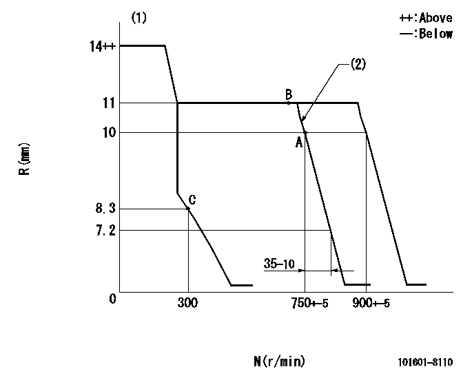
Injection quantity adjustment
Adjusting point
A
Rack position
10
Pump speed
r/min
750
750
750
Average injection quantity
mm3/st.
77.8
76.8
78.8
Max. variation between cylinders
%
0
-2
2
Basic
*
Fixing the rack
*
Injection quantity adjustment_02
Adjusting point
B
Rack position
11
Pump speed
r/min
725
725
725
Average injection quantity
mm3/st.
115
113
117
Max. variation between cylinders
%
0
-4
4
Fixing the lever
*
Injection quantity adjustment_03
Adjusting point
C
Rack position
8.3+-0.5
Pump speed
r/min
300
300
300
Average injection quantity
mm3/st.
10
7.7
12.3
Max. variation between cylinders
%
0
-13
13
Fixing the rack
*
Timer adjustment
Pump speed
r/min
500
Advance angle
deg.
0.3
Timer adjustment_02
Pump speed
r/min
600
Advance angle
deg.
0.8
0.1
0.8
Timer adjustment_03
Pump speed
r/min
700
Advance angle
deg.
0.8
0.3
1.3
Timer adjustment_04
Pump speed
r/min
900
Advance angle
deg.
2
1.5
2.5
Timer adjustment_05
Pump speed
r/min
-
Advance angle
deg.
4
4
4
Remarks
Measure the actual speed, stop
Measure the actual speed, stop
Test data Ex:
Governor adjustment
N:Pump speed
R:Rack position (mm)
(1)Target notch: K
(2)Idle sub spring setting: L1.
----------
K=7 L1=10.5+0.5mm
----------
----------
K=7 L1=10.5+0.5mm
----------
Speed control lever angle
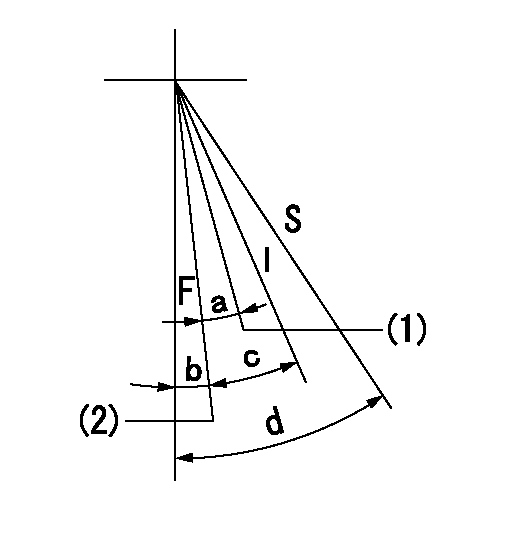
F:Full speed
I:Idle
S:Stop
(1)Pump speed = aa
(2)Speed = bb (at shipping)
----------
aa=750r/min bb=900r/min
----------
a=10deg+-5deg b=4deg+-5deg c=23.5deg+-5deg d=32deg+-3deg
----------
aa=750r/min bb=900r/min
----------
a=10deg+-5deg b=4deg+-5deg c=23.5deg+-5deg d=32deg+-3deg
Stop lever angle
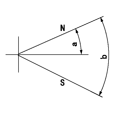
N:Pump normal
S:Stop the pump.
----------
----------
a=10deg+-5deg b=53deg+-5deg
----------
----------
a=10deg+-5deg b=53deg+-5deg
0000001501 LEVER
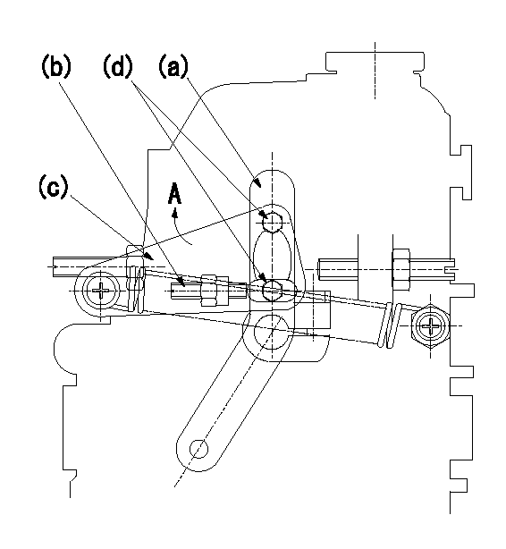
1. Variable lever adjustment
(1)Set lever (a) in the idle position.
(2)Set lever (c) at the dead point using screw (b) and then fix using bolt (d).
(3)When the dead point position cannot be obtained, set the lever (c) at the position closest to the dead point (at the end of the elongated hole) (in the direction of arrow A).
----------
----------
----------
----------
Timing setting

(1)Pump vertical direction
(2)Position of timer's threaded hole at No 1 cylinder's beginning of injection
(3)B.T.D.C.: aa
(4)-
----------
aa=17deg
----------
a=(60deg)
----------
aa=17deg
----------
a=(60deg)
Have questions with 101601-8110?
Group cross 101601-8110 ZEXEL
Isuzu
101601-8110
9 400 619 718
1156014172
INJECTION-PUMP ASSEMBLY
6QA1
6QA1