Rating:
Information injection-pump assembly
ZEXEL
101601-5400
1016015400
Service parts 101601-5400 INJECTION-PUMP ASSEMBLY:
1.
_
7.
COUPLING PLATE
8.
_
9.
_
11.
Nozzle and Holder
23600-2412E
12.
Open Pre:MPa(Kqf/cm2)
16.7{170}/23.5{240}
14.
NOZZLE
Cross reference number
ZEXEL
101601-5400
1016015400
Zexel num
Bosch num
Firm num
Name
101601-5400
INJECTION-PUMP ASSEMBLY
Calibration Data:
Adjustment conditions
Test oil
1404 Test oil ISO4113 or {SAEJ967d}
1404 Test oil ISO4113 or {SAEJ967d}
Test oil temperature
degC
40
40
45
Nozzle and nozzle holder
105780-8140
Bosch type code
EF8511/9A
Nozzle
105780-0000
Bosch type code
DN12SD12T
Nozzle holder
105780-2080
Bosch type code
EF8511/9
Opening pressure
MPa
17.2
Opening pressure
kgf/cm2
175
Injection pipe
Outer diameter - inner diameter - length (mm) mm 6-2-600
Outer diameter - inner diameter - length (mm) mm 6-2-600
Overflow valve
134424-0920
Overflow valve opening pressure
kPa
162
147
177
Overflow valve opening pressure
kgf/cm2
1.65
1.5
1.8
Tester oil delivery pressure
kPa
157
157
157
Tester oil delivery pressure
kgf/cm2
1.6
1.6
1.6
Direction of rotation (viewed from drive side)
Right R
Right R
Injection timing adjustment
Direction of rotation (viewed from drive side)
Right R
Right R
Injection order
1-4-2-6-
3-5
Pre-stroke
mm
3.1
3.07
3.13
Beginning of injection position
Drive side NO.1
Drive side NO.1
Difference between angles 1
Cal 1-4 deg. 60 59.75 60.25
Cal 1-4 deg. 60 59.75 60.25
Difference between angles 2
Cyl.1-2 deg. 120 119.75 120.25
Cyl.1-2 deg. 120 119.75 120.25
Difference between angles 3
Cal 1-6 deg. 180 179.75 180.25
Cal 1-6 deg. 180 179.75 180.25
Difference between angles 4
Cal 1-3 deg. 240 239.75 240.25
Cal 1-3 deg. 240 239.75 240.25
Difference between angles 5
Cal 1-5 deg. 300 299.75 300.25
Cal 1-5 deg. 300 299.75 300.25
Injection quantity adjustment
Adjusting point
-
Rack position
9.4
Pump speed
r/min
900
900
900
Average injection quantity
mm3/st.
70
69
71
Max. variation between cylinders
%
0
-3.5
3.5
Basic
*
Fixing the rack
*
Standard for adjustment of the maximum variation between cylinders
*
Injection quantity adjustment_02
Adjusting point
-
Rack position
7+-0.1
Pump speed
r/min
275
275
275
Average injection quantity
mm3/st.
8
7
9
Max. variation between cylinders
%
0
-10
10
Fixing the rack
*
Standard for adjustment of the maximum variation between cylinders
*
Remarks
Adjust only variation between cylinders; adjust governor according to governor specifications.
Adjust only variation between cylinders; adjust governor according to governor specifications.
Injection quantity adjustment_03
Adjusting point
A
Rack position
R1(9.4)
Pump speed
r/min
900
900
900
Average injection quantity
mm3/st.
70
69
71
Basic
*
Fixing the lever
*
Injection quantity adjustment_04
Adjusting point
I
Rack position
-
Pump speed
r/min
100
100
100
Average injection quantity
mm3/st.
140
140
150
Fixing the lever
*
Rack limit
*
Timer adjustment
Pump speed
r/min
1250--
Advance angle
deg.
0
0
0
Load
3/4
Remarks
Start
Start
Timer adjustment_02
Pump speed
r/min
1200
Advance angle
deg.
0.3
Load
3/4
Timer adjustment_03
Pump speed
r/min
1450
Advance angle
deg.
4
3.5
4.5
Load
4/4
Remarks
Finish
Finish
Test data Ex:
Governor adjustment
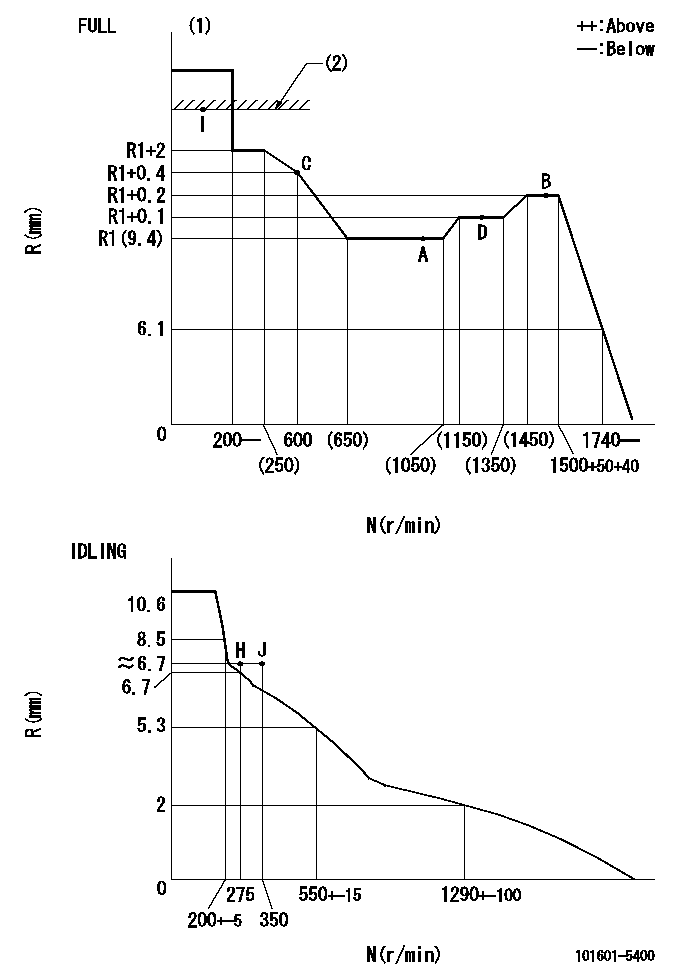
N:Pump speed
R:Rack position (mm)
(1)Torque cam stamping: T1
(2)RACK LIMIT
----------
T1=B94
----------
----------
T1=B94
----------
Speed control lever angle
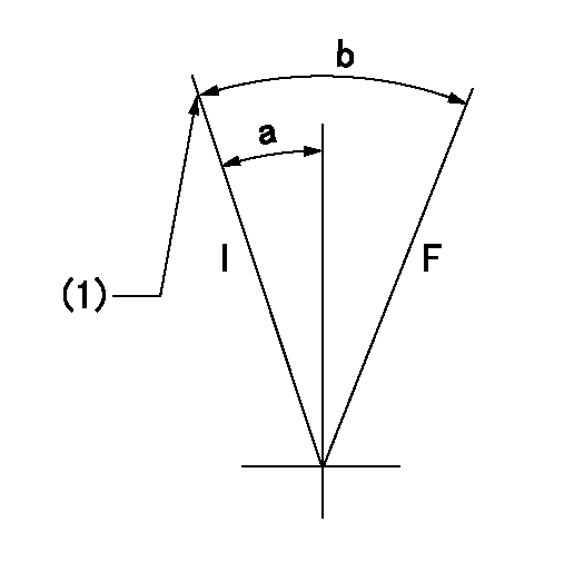
F:Full speed
I:Idle
(1)Stopper bolt setting
----------
----------
a=23deg+-5deg b=(45deg)+-3deg
----------
----------
a=23deg+-5deg b=(45deg)+-3deg
Stop lever angle
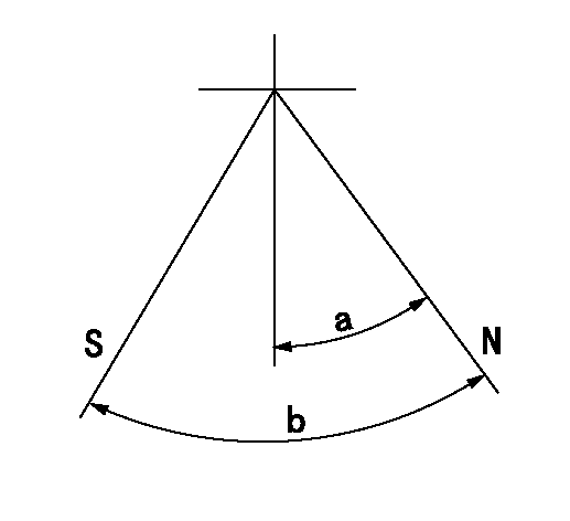
N:Pump normal
S:Stop the pump.
----------
----------
a=14.5deg+-5deg b=40deg+-5deg
----------
----------
a=14.5deg+-5deg b=40deg+-5deg
0000001501 AIR CYLINDER
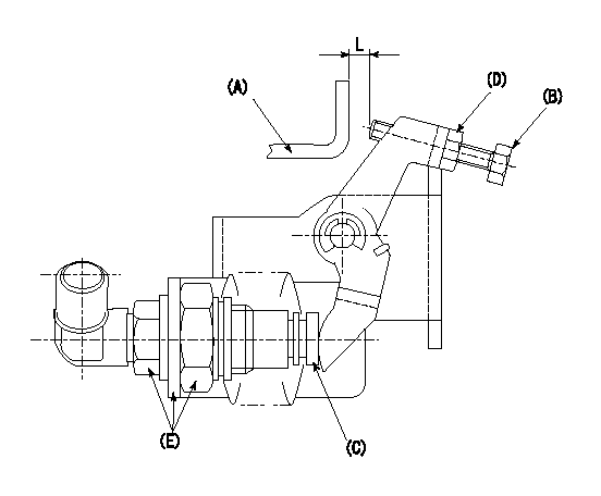
(A): Speed lever
(B): Set bolt
(C): air cylinder
(D): nut
(E): fix
1. Air cylinder adjustment procedure
(1)With the speed lever in the idling position, temporarily set the clearance between speed lever (A) and set bolt (B) at approximately L1.
(2)Set the speed to N1 and supply positive pressure P1 to the air cylinder (C).
(3)Gradually push set bolt (B) out (approximately L2) and tighten nut (D) where the speed is N2 and the rack position is Ra.
(4)Apply positive pressure P1 several times.
(5)Confirm that the lever returns to the idle position at positive pressure P2.
(6)Also, confirm that the rack position is Rb at air pressure P1.
----------
L1=5mm L2=2mm Ra=6.9+-0.1mm Rb=6.9+-0.1mm N1=450r/min N2=450r/min P1=392+98kPa(4+1kgf/cm2) P2=0kPa(0kgf/cm2)
----------
----------
L1=5mm L2=2mm Ra=6.9+-0.1mm Rb=6.9+-0.1mm N1=450r/min N2=450r/min P1=392+98kPa(4+1kgf/cm2) P2=0kPa(0kgf/cm2)
----------
Timing setting
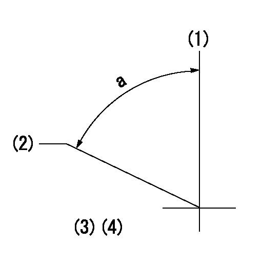
(1)Pump vertical direction
(2)Coupling's key groove position at No 1 cylinder's beginning of injection
(3)-
(4)-
----------
----------
a=(60deg)
----------
----------
a=(60deg)
Have questions with 101601-5400?
Group cross 101601-5400 ZEXEL
101601-5400
INJECTION-PUMP ASSEMBLY