Rating:
Information injection-pump assembly
ZEXEL
101601-5170
1016015170
HINO
220000652B
220000652b
Compare Prices: .
As an associate, we earn commssions on qualifying purchases through the links below

$20.20
08 Jun 2021
US: # 1 Quality Parts
Lube Filter - Baldwin - PT396; Fleetguard - HF6090; Komatsu - 101-60-15170, 101-60-15171, 101-601-5171; Wix - 51534
Parts Express We have the best quality products in all brands, price and excellent after-sales service || Hydraulic and Oil Filter - None
Parts Express We have the best quality products in all brands, price and excellent after-sales service || Hydraulic and Oil Filter - None

$18.62
08 Jun 2021
1.0[0.45] Pounds
US: DB ELECTRICAL STARTE
Complete Tractor New HF3811 Lube Oil Filter Compatible with/Replacement for Komatsu -101-60-15170 101-601-5171 101-60-15171
Complete Tractor Specs: Lube Filter || Compatible with/Replacement for Baldwin: PT396 Fleetguard: HF6090 Komatsu: 101-60-15170, 101-60-15171, 101-601-5171 Wix: 51534 || Compatible With / Replacement For: Komatsu D20A-3 Crawler, D20P-3 Crawler, D20PL-3 Crawler, D20Q-3 Crawler, D20S-3 Crawler, D21A-3 Crawler, D21P-3 Crawler, D21PL-3 Crawler, D21Q-3 Crawler, D21S-3 Crawler, D30A-15 Crawler, D30P-15 Crawler, D30Q-15 Crawler, D30S-15 Crawler, D31A-15 Crawler, D31P-15 Crawler, D31Q-15 Crawler, D31S-15 Crawler, D40A-1 Crawler, D40P-1 Crawler, D40PL-1 Crawler, D40PLL-1 Crawler, D45A-1 Crawler, D45E-1 Crawler, D45P-1 Crawler, D45S-1 Crawler, D50A-16 Crawler || 1-year warranty covers you throughout planting and harvesting seasons || 100% new Lube Filter meets OEM quality for tractors and farm equipment
Complete Tractor Specs: Lube Filter || Compatible with/Replacement for Baldwin: PT396 Fleetguard: HF6090 Komatsu: 101-60-15170, 101-60-15171, 101-601-5171 Wix: 51534 || Compatible With / Replacement For: Komatsu D20A-3 Crawler, D20P-3 Crawler, D20PL-3 Crawler, D20Q-3 Crawler, D20S-3 Crawler, D21A-3 Crawler, D21P-3 Crawler, D21PL-3 Crawler, D21Q-3 Crawler, D21S-3 Crawler, D30A-15 Crawler, D30P-15 Crawler, D30Q-15 Crawler, D30S-15 Crawler, D31A-15 Crawler, D31P-15 Crawler, D31Q-15 Crawler, D31S-15 Crawler, D40A-1 Crawler, D40P-1 Crawler, D40PL-1 Crawler, D40PLL-1 Crawler, D45A-1 Crawler, D45E-1 Crawler, D45P-1 Crawler, D45S-1 Crawler, D50A-16 Crawler || 1-year warranty covers you throughout planting and harvesting seasons || 100% new Lube Filter meets OEM quality for tractors and farm equipment
Cross reference number
ZEXEL
101601-5170
1016015170
HINO
220000652B
220000652b
Zexel num
Bosch num
Firm num
Name
Calibration Data:
Adjustment conditions
Test oil
1404 Test oil ISO4113 or {SAEJ967d}
1404 Test oil ISO4113 or {SAEJ967d}
Test oil temperature
degC
40
40
45
Nozzle and nozzle holder
105780-8140
Bosch type code
EF8511/9A
Nozzle
105780-0000
Bosch type code
DN12SD12T
Nozzle holder
105780-2080
Bosch type code
EF8511/9
Opening pressure
MPa
17.2
Opening pressure
kgf/cm2
175
Injection pipe
Outer diameter - inner diameter - length (mm) mm 6-2-600
Outer diameter - inner diameter - length (mm) mm 6-2-600
Overflow valve
134424-0920
Overflow valve opening pressure
kPa
162
147
177
Overflow valve opening pressure
kgf/cm2
1.65
1.5
1.8
Tester oil delivery pressure
kPa
157
157
157
Tester oil delivery pressure
kgf/cm2
1.6
1.6
1.6
Direction of rotation (viewed from drive side)
Right R
Right R
Injection timing adjustment
Direction of rotation (viewed from drive side)
Right R
Right R
Injection order
1-4-2-6-
3-5
Pre-stroke
mm
3.1
3.07
3.13
Beginning of injection position
Drive side NO.1
Drive side NO.1
Difference between angles 1
Cal 1-4 deg. 60 59.75 60.25
Cal 1-4 deg. 60 59.75 60.25
Difference between angles 2
Cyl.1-2 deg. 120 119.75 120.25
Cyl.1-2 deg. 120 119.75 120.25
Difference between angles 3
Cal 1-6 deg. 180 179.75 180.25
Cal 1-6 deg. 180 179.75 180.25
Difference between angles 4
Cal 1-3 deg. 240 239.75 240.25
Cal 1-3 deg. 240 239.75 240.25
Difference between angles 5
Cal 1-5 deg. 300 299.75 300.25
Cal 1-5 deg. 300 299.75 300.25
Injection quantity adjustment
Adjusting point
-
Rack position
8.9
Pump speed
r/min
900
900
900
Average injection quantity
mm3/st.
64.6
63.6
65.6
Max. variation between cylinders
%
0
-3.5
3.5
Basic
*
Fixing the rack
*
Standard for adjustment of the maximum variation between cylinders
*
Injection quantity adjustment_02
Adjusting point
-
Rack position
7.2+-0.5
Pump speed
r/min
375
375
375
Average injection quantity
mm3/st.
7.5
6.5
8.5
Max. variation between cylinders
%
0
-10
10
Fixing the rack
*
Standard for adjustment of the maximum variation between cylinders
*
Remarks
Adjust only variation between cylinders; adjust governor according to governor specifications.
Adjust only variation between cylinders; adjust governor according to governor specifications.
Injection quantity adjustment_03
Adjusting point
A
Rack position
R1(8.9)
Pump speed
r/min
900
900
900
Average injection quantity
mm3/st.
64.6
63.6
65.6
Basic
*
Fixing the lever
*
Injection quantity adjustment_04
Adjusting point
I
Rack position
-
Pump speed
r/min
100
100
100
Average injection quantity
mm3/st.
105.5
105.5
Fixing the lever
*
Timer adjustment
Pump speed
r/min
1250--
Advance angle
deg.
0
0
0
Remarks
Start
Start
Timer adjustment_02
Pump speed
r/min
1200
Advance angle
deg.
0.5
Timer adjustment_03
Pump speed
r/min
1500
Advance angle
deg.
3.5
3.2
3.8
Remarks
Finish
Finish
Test data Ex:
Governor adjustment
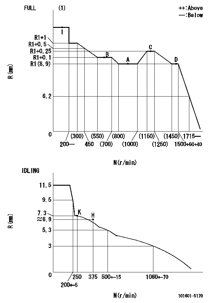
N:Pump speed
R:Rack position (mm)
(1)Torque cam stamping: T1
----------
T1=B70
----------
----------
T1=B70
----------
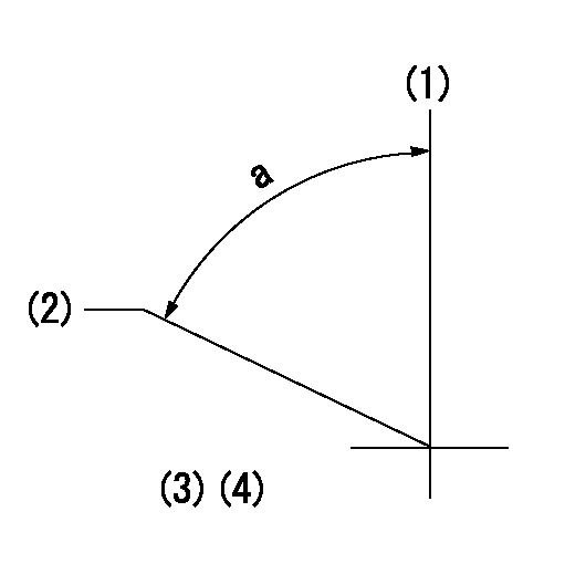
Speed control lever angle
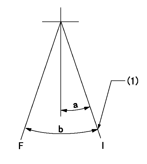
F:Full speed
I:Idle
(1)Stopper bolt set position 'K'
----------
----------
a=30deg+-5deg b=41deg+-3deg
----------
----------
a=30deg+-5deg b=41deg+-3deg
Stop lever angle
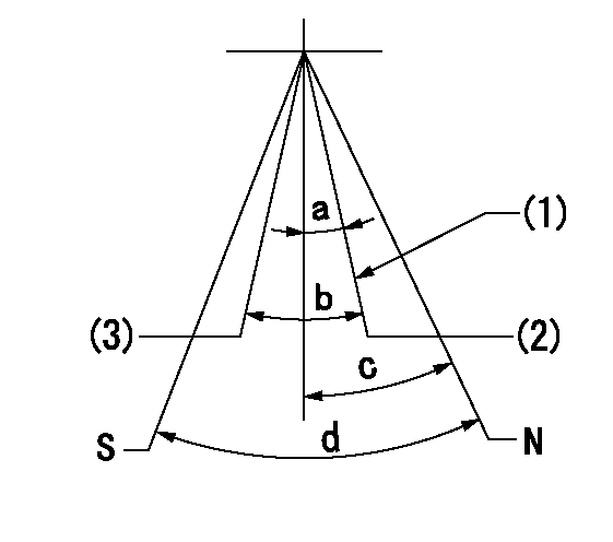
N:Pump normal
S:Stop the pump.
(1)Set the normal set bolt.
(2)Engine normal
(3)Engine stop
----------
----------
a=(0deg)+-5deg b=(13deg) c=16deg+-5deg d=40deg+-5deg
----------
----------
a=(0deg)+-5deg b=(13deg) c=16deg+-5deg d=40deg+-5deg
Timing setting
(1)Pump vertical direction
(2)Coupling's key groove position at No 1 cylinder's beginning of injection
(3)-
(4)-
----------
----------
a=(55deg)
----------
----------
a=(55deg)