
Rating:
Information injection-pump assembly
BOSCH
9 400 614 598
9400614598
ZEXEL
101601-5073
1016015073
HINO
220801321A
220801321a
Include in #1:
106682-9340
as _
Cross reference number
BOSCH
9 400 614 598
9400614598
ZEXEL
101601-5073
1016015073
HINO
220801321A
220801321a
Zexel num
Bosch num
Firm num
Name
101601-5073
9 400 614 598
220801321A HINO
INJECTION-PUMP ASSEMBLY
W06D K
W06D K
Calibration Data:
Adjustment conditions
Test oil
1404 Test oil ISO4113 or {SAEJ967d}
1404 Test oil ISO4113 or {SAEJ967d}
Test oil temperature
degC
40
40
45
Nozzle and nozzle holder
105780-8140
Bosch type code
EF8511/9A
Nozzle
105780-0000
Bosch type code
DN12SD12T
Nozzle holder
105780-2080
Bosch type code
EF8511/9
Opening pressure
MPa
17.2
Opening pressure
kgf/cm2
175
Injection pipe
Outer diameter - inner diameter - length (mm) mm 6-2-600
Outer diameter - inner diameter - length (mm) mm 6-2-600
Overflow valve
131424-5720
Overflow valve opening pressure
kPa
255
221
289
Overflow valve opening pressure
kgf/cm2
2.6
2.25
2.95
Tester oil delivery pressure
kPa
157
157
157
Tester oil delivery pressure
kgf/cm2
1.6
1.6
1.6
Direction of rotation (viewed from drive side)
Right R
Right R
Injection timing adjustment
Direction of rotation (viewed from drive side)
Right R
Right R
Injection order
1-4-2-6-
3-5
Pre-stroke
mm
3.1
3.07
3.13
Beginning of injection position
Drive side NO.1
Drive side NO.1
Difference between angles 1
Cal 1-4 deg. 60 59.75 60.25
Cal 1-4 deg. 60 59.75 60.25
Difference between angles 2
Cyl.1-2 deg. 120 119.75 120.25
Cyl.1-2 deg. 120 119.75 120.25
Difference between angles 3
Cal 1-6 deg. 180 179.75 180.25
Cal 1-6 deg. 180 179.75 180.25
Difference between angles 4
Cal 1-3 deg. 240 239.75 240.25
Cal 1-3 deg. 240 239.75 240.25
Difference between angles 5
Cal 1-5 deg. 300 299.75 300.25
Cal 1-5 deg. 300 299.75 300.25
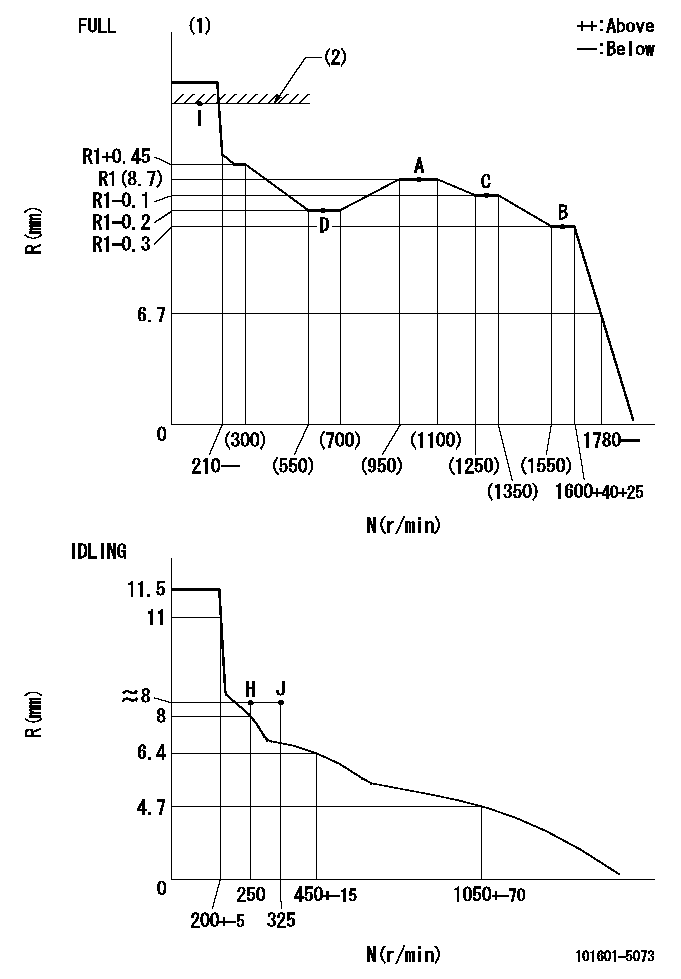
Injection quantity adjustment
Adjusting point
-
Rack position
8.7
Pump speed
r/min
1000
1000
1000
Average injection quantity
mm3/st.
44.4
42.4
46.4
Max. variation between cylinders
%
0
-3.5
3.5
Basic
*
Fixing the rack
*
Standard for adjustment of the maximum variation between cylinders
*
Injection quantity adjustment_02
Adjusting point
H
Rack position
8+-0.5
Pump speed
r/min
250
250
250
Average injection quantity
mm3/st.
8
6.5
9.5
Max. variation between cylinders
%
0
-10
10
Fixing the rack
*
Standard for adjustment of the maximum variation between cylinders
*
Injection quantity adjustment_03
Adjusting point
A
Rack position
R1(8.7)
Pump speed
r/min
1000
1000
1000
Average injection quantity
mm3/st.
44.4
43.4
45.4
Basic
*
Fixing the lever
*
Injection quantity adjustment_04
Adjusting point
B
Rack position
R1-0.3
Pump speed
r/min
1600
1600
1600
Average injection quantity
mm3/st.
43.5
41.5
45.5
Fixing the lever
*
Injection quantity adjustment_05
Adjusting point
C
Rack position
R1-0.1
Pump speed
r/min
1300
1300
1300
Average injection quantity
mm3/st.
44.1
42.1
46.1
Fixing the lever
*
Injection quantity adjustment_06
Adjusting point
D
Rack position
R1-0.2
Pump speed
r/min
650
650
650
Average injection quantity
mm3/st.
36.2
34.2
38.2
Fixing the lever
*
Injection quantity adjustment_07
Adjusting point
I
Rack position
13.5+-0.
5
Pump speed
r/min
100
100
100
Average injection quantity
mm3/st.
95
95
105
Fixing the lever
*
Rack limit
*
Timer adjustment
Pump speed
r/min
1300+50
Advance angle
deg.
0
0
0
Remarks
Start
Start
Timer adjustment_02
Pump speed
r/min
1600
Advance angle
deg.
5
4.7
5.3
Remarks
Finish
Finish
Test data Ex:
Governor adjustment
N:Pump speed
R:Rack position (mm)
(1)Torque cam stamping: T1
(2)RACK LIMIT
----------
T1=93
----------
----------
T1=93
----------
Speed control lever angle
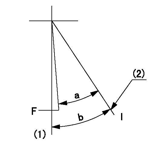
F:Full speed
I:Idle
(1)-
(2)Stopper bolt setting
----------
----------
a=32.5deg+-3deg b=34deg+-5deg
----------
----------
a=32.5deg+-3deg b=34deg+-5deg
Stop lever angle
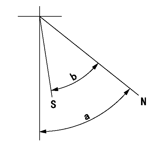
N:Pump normal
S:Stop the pump.
----------
----------
a=40deg+-5deg b=40deg+-5deg
----------
----------
a=40deg+-5deg b=40deg+-5deg
0000001501 ACTUATOR
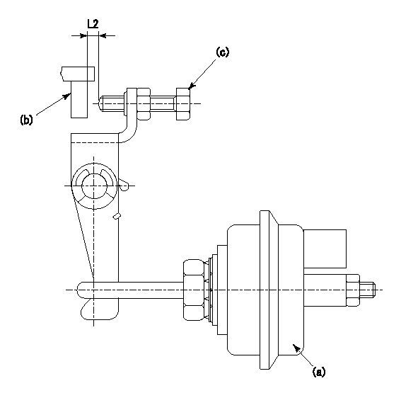
(a) actuator
(b) Speed lever
(c) set bolt
(d) control lever
1. Actuator adjustment procedure
(1)Apply negative pressure P1 to the actuator (a) and confirm that the stroke is approximately L1.
(2)Set the speed lever (b) at the idling position (N = 0).
(3)Set temporarily so that the clearance from the set bolt is approximately L2.
(4)Set the pump speed at N1 and apply negative pressure P2.
(5)Adjust set bolt (c) so that the rack position is R1 to R2.
(6)Set the pump speed at N2 and apply negative pressure P3.
(7)At this time, confirm that the speed lever (b) moves smoothly and that the rack position becomes R1 to R2.
----------
L1=10mm L2=2mm P1=66.7kPa(500mmHg) P2=66.7kPa(500mmHg) P3=66.7kPa(500mmHg) N1=250r/min N2=250r/min R1=8.4mm R2=8.7mm
----------
----------
L1=10mm L2=2mm P1=66.7kPa(500mmHg) P2=66.7kPa(500mmHg) P3=66.7kPa(500mmHg) N1=250r/min N2=250r/min R1=8.4mm R2=8.7mm
----------
Timing setting

(1)Pump vertical direction
(2)Position of gear's standard threaded hole at No 1 cylinder's beginning of injection
(3)-
(4)-
----------
----------
a=(70deg)
----------
----------
a=(70deg)
Have questions with 101601-5073?
Group cross 101601-5073 ZEXEL
Hino
Hino
Hino
Hino
Hino
Hino
Hino
101601-5073
9 400 614 598
220801321A
INJECTION-PUMP ASSEMBLY
W06D
W06D