Rating:
Information injection-pump assembly
BOSCH
9 400 613 162
9400613162
ZEXEL
101601-3220
1016013220
KOMATSU
6138721120
6138721120
Service parts 101601-3220 INJECTION-PUMP ASSEMBLY:
1.
_
7.
COUPLING PLATE
8.
_
9.
_
11.
Nozzle and Holder
6138-12-3300
12.
Open Pre:MPa(Kqf/cm2)
24.5{250}
15.
NOZZLE SET
Cross reference number
BOSCH
9 400 613 162
9400613162
ZEXEL
101601-3220
1016013220
KOMATSU
6138721120
6138721120
Zexel num
Bosch num
Firm num
Name
101601-3220
9 400 613 162
6138721120 KOMATSU
INJECTION-PUMP ASSEMBLY
SA6D110 K 14BF INJECTION PUMP ASSY PE6AD PE
SA6D110 K 14BF INJECTION PUMP ASSY PE6AD PE
Calibration Data:
Adjustment conditions
Test oil
1404 Test oil ISO4113 or {SAEJ967d}
1404 Test oil ISO4113 or {SAEJ967d}
Test oil temperature
degC
40
40
45
Nozzle and nozzle holder
105780-8140
Bosch type code
EF8511/9A
Nozzle
105780-0000
Bosch type code
DN12SD12T
Nozzle holder
105780-2080
Bosch type code
EF8511/9
Opening pressure
MPa
17.2
Opening pressure
kgf/cm2
175
Injection pipe
Outer diameter - inner diameter - length (mm) mm 6-2-600
Outer diameter - inner diameter - length (mm) mm 6-2-600
Tester oil delivery pressure
kPa
157
157
157
Tester oil delivery pressure
kgf/cm2
1.6
1.6
1.6
Direction of rotation (viewed from drive side)
Right R
Right R
Injection timing adjustment
Direction of rotation (viewed from drive side)
Right R
Right R
Injection order
1-5-3-6-
2-4
Pre-stroke
mm
4
3.95
4.05
Beginning of injection position
Drive side NO.1
Drive side NO.1
Difference between angles 1
Cal 1-5 deg. 60 59.5 60.5
Cal 1-5 deg. 60 59.5 60.5
Difference between angles 2
Cal 1-3 deg. 120 119.5 120.5
Cal 1-3 deg. 120 119.5 120.5
Difference between angles 3
Cal 1-6 deg. 180 179.5 180.5
Cal 1-6 deg. 180 179.5 180.5
Difference between angles 4
Cyl.1-2 deg. 240 239.5 240.5
Cyl.1-2 deg. 240 239.5 240.5
Difference between angles 5
Cal 1-4 deg. 300 299.5 300.5
Cal 1-4 deg. 300 299.5 300.5
Injection quantity adjustment
Adjusting point
A
Rack position
10.5
Pump speed
r/min
1100
1100
1100
Average injection quantity
mm3/st.
85.8
84.8
86.8
Max. variation between cylinders
%
0
-2
2
Basic
*
Fixing the lever
*
Boost pressure
kPa
40
40
Boost pressure
mmHg
300
300
Injection quantity adjustment_02
Adjusting point
B
Rack position
7.4+-0.5
Pump speed
r/min
375
375
375
Average injection quantity
mm3/st.
15.5
14.3
16.7
Max. variation between cylinders
%
0
-10
10
Fixing the rack
*
Boost pressure
kPa
0
0
0
Boost pressure
mmHg
0
0
0
Boost compensator adjustment
Pump speed
r/min
600
600
600
Rack position
10.5
Boost pressure
kPa
10.7
8
13.4
Boost pressure
mmHg
80
60
100
Boost compensator adjustment_02
Pump speed
r/min
600
600
600
Rack position
11.5
Boost pressure
kPa
26.7
26.7
26.7
Boost pressure
mmHg
200
200
200
Timer adjustment
Pump speed
r/min
750--
Advance angle
deg.
0
0
0
Remarks
Start
Start
Timer adjustment_02
Pump speed
r/min
700
Advance angle
deg.
0.5
Timer adjustment_03
Pump speed
r/min
900
Advance angle
deg.
1.4
0.9
1.9
Timer adjustment_04
Pump speed
r/min
1100
Advance angle
deg.
2.8
2.3
3.3
Timer adjustment_05
Pump speed
r/min
-
Advance angle
deg.
5
4.5
5.5
Remarks
Measure the actual speed, stop
Measure the actual speed, stop
Test data Ex:
Governor adjustment
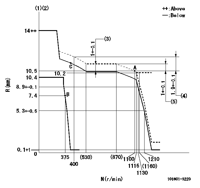
N:Pump speed
R:Rack position (mm)
(1)Target notch: K
(2)Tolerance for racks not indicated: +-0.05mm.
(3)Boost compensator stroke
(4)Rack difference between N = N1 and N = N2
(5)Rack difference between N = N3 and N = N4
----------
K=16 N1=1100r/min N2=400r/min N3=1100r/min N4=750r/min
----------
----------
K=16 N1=1100r/min N2=400r/min N3=1100r/min N4=750r/min
----------
Speed control lever angle
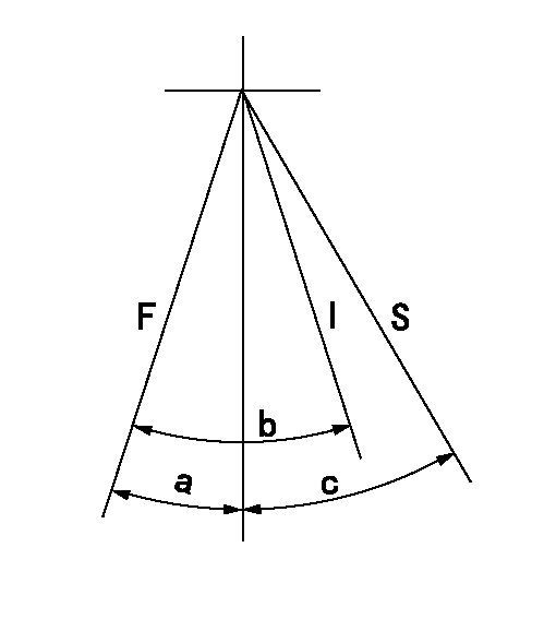
F:Full speed
I:Idle
S:Stop
----------
----------
a=8deg+-5deg b=23deg+-5deg c=32deg+-3deg
----------
----------
a=8deg+-5deg b=23deg+-5deg c=32deg+-3deg
0000001501 LEVER
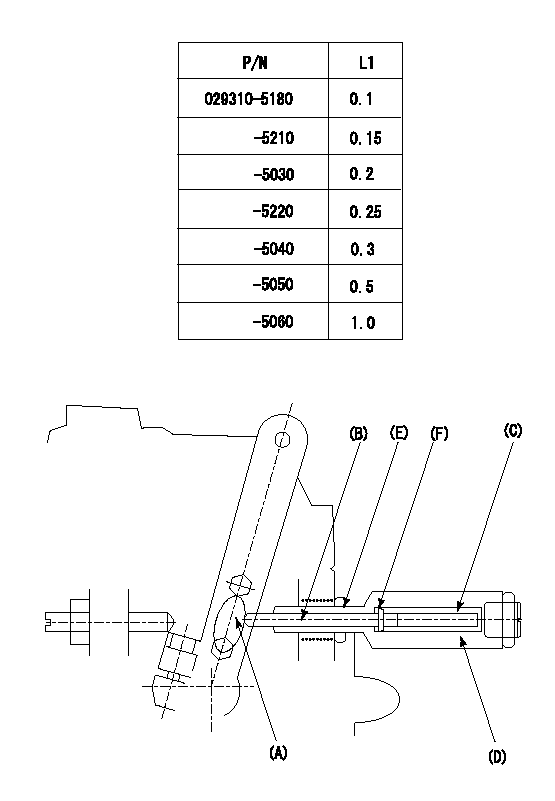
(F) P/N: Part number of the shim
L1:Thickness (mm)
1. Adjustment of the control lever
(1)Perform idling with the control lever (A) contacting the pushrod (B). At this time, confirm that the spring (C) is not compressed by control lever (A)'s operating torque.
(2)To set the stop position, compress spring (C) using the control lever (A) and adjust the rack so that it contacts the guide screw (D) at position L2. Then, set and fix using the lock nut (E). Adjust the rack position L2 at this time using the shim (F).
(3)Confirm that the control lever (A) returns to the idling position when pulled in the stop direction and then released.
----------
L2=0.2~2mm
----------
----------
L2=0.2~2mm
----------
Timing setting

(1)Pump vertical direction
(2)Coupling's key groove position at No 1 cylinder's beginning of injection
(3)-
(4)-
----------
----------
a=(0deg)
----------
----------
a=(0deg)
Have questions with 101601-3220?
Group cross 101601-3220 ZEXEL
Komatsu
101601-3220
9 400 613 162
6138721120
INJECTION-PUMP ASSEMBLY
SA6D110
SA6D110