Rating:
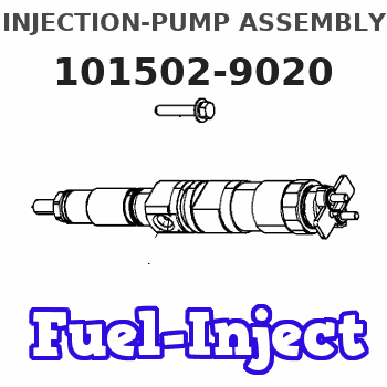
Information injection-pump assembly
ZEXEL
101502-9020
1015029020
Service parts 101502-9020 INJECTION-PUMP ASSEMBLY:
1.
_
6.
COUPLING PLATE
7.
COUPLING PLATE
8.
_
9.
_
11.
Nozzle and Holder
157-0753-001
12.
Open Pre:MPa(Kqf/cm2)
15.7{160}/22.1{225}
15.
NOZZLE SET
Cross reference number
ZEXEL
101502-9020
1015029020
Zexel num
Bosch num
Firm num
Name
101502-9020
INJECTION-PUMP ASSEMBLY
Calibration Data:
Adjustment conditions
Test oil
1404 Test oil ISO4113 or {SAEJ967d}
1404 Test oil ISO4113 or {SAEJ967d}
Test oil temperature
degC
40
40
45
Nozzle and nozzle holder
105780-8140
Bosch type code
EF8511/9A
Nozzle
105780-0000
Bosch type code
DN12SD12T
Nozzle holder
105780-2080
Bosch type code
EF8511/9
Opening pressure
MPa
17.2
Opening pressure
kgf/cm2
175
Injection pipe
Outer diameter - inner diameter - length (mm) mm 6-2-600
Outer diameter - inner diameter - length (mm) mm 6-2-600
Overflow valve
131424-4320
Overflow valve opening pressure
kPa
157
123
191
Overflow valve opening pressure
kgf/cm2
1.6
1.25
1.95
Tester oil delivery pressure
kPa
157
157
157
Tester oil delivery pressure
kgf/cm2
1.6
1.6
1.6
Direction of rotation (viewed from drive side)
Left L
Left L
Injection timing adjustment
Direction of rotation (viewed from drive side)
Left L
Left L
Injection order
1-3-5-4-
2
Pre-stroke
mm
3.6
3.55
3.65
Beginning of injection position
Drive side NO.1
Drive side NO.1
Difference between angles 1
Cal 1-3 deg. 72 71.5 72.5
Cal 1-3 deg. 72 71.5 72.5
Difference between angles 2
Cal 1-5 deg. 144 143.5 144.5
Cal 1-5 deg. 144 143.5 144.5
Difference between angles 3
Cal 1-4 deg. 216 215.5 216.5
Cal 1-4 deg. 216 215.5 216.5
Difference between angles 4
Cyl.1-2 deg. 288 287.5 288.5
Cyl.1-2 deg. 288 287.5 288.5
Injection quantity adjustment
Adjusting point
A
Rack position
10.9
Pump speed
r/min
1200
1200
1200
Average injection quantity
mm3/st.
83.8
82.3
85.3
Max. variation between cylinders
%
0
-2.5
2.5
Basic
*
Fixing the lever
*
Injection quantity adjustment_02
Adjusting point
B
Rack position
7.3+-0.5
Pump speed
r/min
300
300
300
Average injection quantity
mm3/st.
10
8
12
Max. variation between cylinders
%
0
-15
15
Fixing the rack
*
Test data Ex:
Governor adjustment
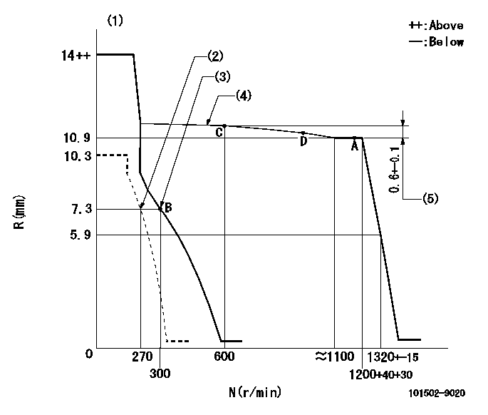
N:Pump speed
R:Rack position (mm)
(1)Target notch: K
(2)Set idle sub-spring
(3)Main spring setting
(4)The torque control spring must does not have a set force.
(5)Rack difference between N = N1 and N = N2
----------
K=14 N1=1200r/min N2=600r/min
----------
----------
K=14 N1=1200r/min N2=600r/min
----------
Speed control lever angle
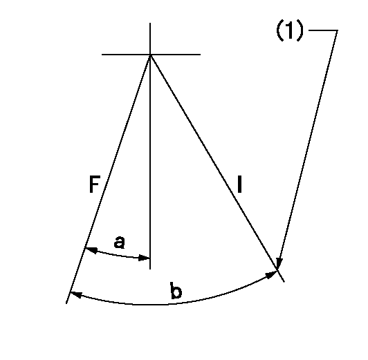
F:Full speed
I:Idle
(1)Stopper bolt setting
----------
----------
a=(23deg)+-5deg b=(37deg)+-5deg
----------
----------
a=(23deg)+-5deg b=(37deg)+-5deg
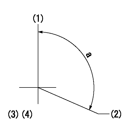
Stop lever angle
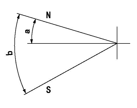
N:Pump normal
S:Stop the pump.
----------
----------
a=19deg+-5deg b=53deg+-5deg
----------
----------
a=19deg+-5deg b=53deg+-5deg
Timing setting
(1)Pump vertical direction
(2)Position of camshaft's key groove at No 1 cylinder's beginning of injection
(3)-
(4)-
----------
----------
a=(120deg)
----------
----------
a=(120deg)
Have questions with 101502-9020?
Group cross 101502-9020 ZEXEL
101502-9020
INJECTION-PUMP ASSEMBLY