Rating:
Information injection-pump assembly
ZEXEL
101501-2021
1015012021
HINO
220008710B
220008710b
Service parts 101501-2021 INJECTION-PUMP ASSEMBLY:
1.
_
7.
COUPLING PLATE
8.
_
9.
_
11.
Nozzle and Holder
23600-2663
12.
Open Pre:MPa(Kqf/cm2)
16.7{170}/21.6{220}
14.
NOZZLE
Include in #1:
101501-2021
as INJECTION-PUMP ASSEMBLY
Include in #2:
104761-4013
as _
Cross reference number
ZEXEL
101501-2021
1015012021
HINO
220008710B
220008710b
Zexel num
Bosch num
Firm num
Name
Calibration Data:
Adjustment conditions
Test oil
1404 Test oil ISO4113 or {SAEJ967d}
1404 Test oil ISO4113 or {SAEJ967d}
Test oil temperature
degC
40
40
45
Nozzle and nozzle holder
105780-8250
Bosch type code
1 688 901 101
Nozzle
105780-0120
Bosch type code
1 688 901 990
Nozzle holder
105780-2190
Opening pressure
MPa
20.7
Opening pressure
kgf/cm2
211
Injection pipe
Outer diameter - inner diameter - length (mm) mm 6-2-600
Outer diameter - inner diameter - length (mm) mm 6-2-600
Overflow valve
131425-0320
Overflow valve opening pressure
kPa
108
88
128
Overflow valve opening pressure
kgf/cm2
1.1
0.9
1.3
Tester oil delivery pressure
kPa
255
255
255
Tester oil delivery pressure
kgf/cm2
2.6
2.6
2.6
Direction of rotation (viewed from drive side)
Left L
Left L
Injection timing adjustment
Direction of rotation (viewed from drive side)
Left L
Left L
Injection order
1-2-4-5-
3
Pre-stroke
mm
4
3.97
4.03
Beginning of injection position
Governor side NO.1
Governor side NO.1
Difference between angles 1
Cyl.1-2 deg. 72 71.75 72.25
Cyl.1-2 deg. 72 71.75 72.25
Difference between angles 2
Cal 1-4 deg. 144 143.75 144.25
Cal 1-4 deg. 144 143.75 144.25
Difference between angles 3
Cal 1-5 deg. 216 215.75 216.25
Cal 1-5 deg. 216 215.75 216.25
Difference between angles 4
Cal 1-3 deg. 288 287.75 288.25
Cal 1-3 deg. 288 287.75 288.25
Injection quantity adjustment
Adjusting point
-
Rack position
12.2
Pump speed
r/min
850
850
850
Average injection quantity
mm3/st.
100
98.4
101.6
Max. variation between cylinders
%
0
-3.5
3.5
Basic
*
Fixing the rack
*
Standard for adjustment of the maximum variation between cylinders
*
Injection quantity adjustment_02
Adjusting point
Z
Rack position
9.5+-0.5
Pump speed
r/min
415
415
415
Each cylinder's injection qty
mm3/st.
12
11
13
Fixing the rack
*
Standard for adjustment of the maximum variation between cylinders
*
Injection quantity adjustment_03
Adjusting point
A
Rack position
R1(12.2)
Pump speed
r/min
850
850
850
Average injection quantity
mm3/st.
100
99
101
Basic
*
Fixing the lever
*
Injection quantity adjustment_04
Adjusting point
B
Rack position
R1+0.6
Pump speed
r/min
1450
1450
1450
Average injection quantity
mm3/st.
103
99
107
Fixing the lever
*
Injection quantity adjustment_05
Adjusting point
C
Rack position
R1+0.45
Pump speed
r/min
1160
1160
1160
Average injection quantity
mm3/st.
105.5
101.5
109.5
Fixing the lever
*
Injection quantity adjustment_06
Adjusting point
D
Rack position
R1-0.75
Pump speed
r/min
580
580
580
Average injection quantity
mm3/st.
84
80
88
Fixing the lever
*
Injection quantity adjustment_07
Adjusting point
E
Rack position
R1-0.9
Pump speed
r/min
300
300
300
Average injection quantity
mm3/st.
77
71
83
Fixing the lever
*
Injection quantity adjustment_08
Adjusting point
I
Rack position
-
Pump speed
r/min
100
100
100
Average injection quantity
mm3/st.
170
170
180
Fixing the lever
*
Rack limit
*
Timer adjustment
Pump speed
r/min
950--
Advance angle
deg.
0
0
0
Load
1/5
Remarks
Start
Start
Timer adjustment_02
Pump speed
r/min
900
Advance angle
deg.
0.3
Load
1/5
Timer adjustment_03
Pump speed
r/min
-
Advance angle
deg.
1
0.7
1.3
Load
5/5
Remarks
Measure the actual speed.
Measure the actual speed.
Timer adjustment_04
Pump speed
r/min
1190++
Advance angle
deg.
1
0.7
1.3
Load
2/5
Timer adjustment_05
Pump speed
r/min
(1300-50
)
Advance angle
deg.
1
0.7
1.3
Load
5/5
Remarks
Measure the actual speed.
Measure the actual speed.
Timer adjustment_06
Pump speed
r/min
1450-50
Advance angle
deg.
5.5
5.2
5.8
Load
5/5
Remarks
Finish
Finish
Test data Ex:
Governor adjustment
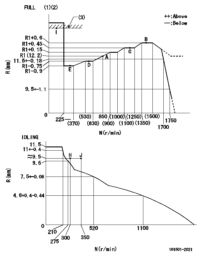
N:Pump speed
R:Rack position (mm)
(1)Torque cam stamping: T1
(2)Tolerance for racks not indicated: +-0.05mm.
(3)RACK LIMIT
----------
T1=K70
----------
----------
T1=K70
----------
Speed control lever angle
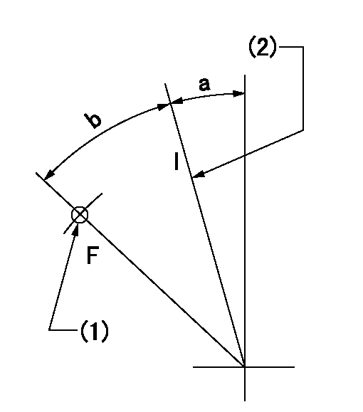
F:Full speed
I:Idle
(1)Use the hole at R = aa
(2)Stopper bolt set position 'H'
----------
aa=41mm
----------
a=8deg+-5deg b=(47deg)+-3deg
----------
aa=41mm
----------
a=8deg+-5deg b=(47deg)+-3deg
Stop lever angle
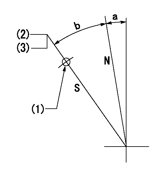
N:Pump normal
S:Stop the pump.
(1)Use the hole at R = aa
(2)Set the stopper bolt so that speed = bb and rack position = cc. Confirm non-injection.
(3)After setting the stopper screw, confirm non-injection at N = dd and R = actual rack position. After setting apply red paint.
----------
aa=38mm bb=1750r/min cc=6.8-0.5mm dd=300r/min
----------
a=0deg+-5deg b=(28deg)+-5deg
----------
aa=38mm bb=1750r/min cc=6.8-0.5mm dd=300r/min
----------
a=0deg+-5deg b=(28deg)+-5deg
Timing setting
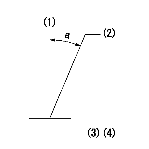
(1)Pump vertical direction
(2)Coupling's key groove position at No 1 cylinder's beginning of injection
(3)-
(4)-
----------
----------
a=(20deg)
----------
----------
a=(20deg)