
Rating:
Information injection-pump assembly
BOSCH
9 400 614 531
9400614531
ZEXEL
101495-3428
1014953428
KOMATSU
6205711151
6205711151
Compare Prices: .
As an associate, we earn commssions on qualifying purchases through the links below

$1,235.18
29 Jul 2020
0.881849048[0.00] Pounds
-: -
Bosch 9 400 614 531 Fuel Injection Pump
Bosch || Fuel Injection Pump || Original Manufacturer
Bosch || Fuel Injection Pump || Original Manufacturer
Service parts 101495-3428 INJECTION-PUMP ASSEMBLY:
1.
_

5.
AUTOM. ADVANCE MECHANIS
6.
COUPLING PLATE
7.
COUPLING PLATE
8.
_
9.
_
11.
Nozzle and Holder
12.
Open Pre:MPa(Kqf/cm2)
19.6{200}
15.
NOZZLE SET
Include in #1:
101495-3428
as INJECTION-PUMP ASSEMBLY
101495-3428
as _
Cross reference number
BOSCH
9 400 614 531
9400614531
ZEXEL
101495-3428
1014953428
KOMATSU
6205711151
6205711151
Zexel num
Bosch num
Firm num
Name
101495-3428
9 400 614 531
6205711151 KOMATSU
INJECTION-PUMP ASSEMBLY
S4D95LE-2 K 14BC INJECTION PUMP ASSY PE4A,5A, PE
S4D95LE-2 K 14BC INJECTION PUMP ASSY PE4A,5A, PE
Calibration Data:
Adjustment conditions
Test oil
1404 Test oil ISO4113 or {SAEJ967d}
1404 Test oil ISO4113 or {SAEJ967d}
Test oil temperature
degC
40
40
45
Nozzle and nozzle holder
105780-8140
Bosch type code
EF8511/9A
Nozzle
105780-0000
Bosch type code
DN12SD12T
Nozzle holder
105780-2080
Bosch type code
EF8511/9
Opening pressure
MPa
17.2
Opening pressure
kgf/cm2
175
Injection pipe
Outer diameter - inner diameter - length (mm) mm 6-2-600
Outer diameter - inner diameter - length (mm) mm 6-2-600
Tester oil delivery pressure
kPa
157
157
157
Tester oil delivery pressure
kgf/cm2
1.6
1.6
1.6
Direction of rotation (viewed from drive side)
Right R
Right R
Injection timing adjustment
Direction of rotation (viewed from drive side)
Right R
Right R
Injection order
1-2-4-3
Pre-stroke
mm
3.2
3.15
3.25
Rack position
After adjusting injection quantity. R=A
After adjusting injection quantity. R=A
Beginning of injection position
Drive side NO.1
Drive side NO.1
Difference between angles 1
Cyl.1-2 deg. 90 89.5 90.5
Cyl.1-2 deg. 90 89.5 90.5
Difference between angles 2
Cal 1-4 deg. 180 179.5 180.5
Cal 1-4 deg. 180 179.5 180.5
Difference between angles 3
Cal 1-3 deg. 270 269.5 270.5
Cal 1-3 deg. 270 269.5 270.5
Injection quantity adjustment
Adjusting point
A
Rack position
11.3
Pump speed
r/min
900
900
900
Average injection quantity
mm3/st.
91.5
90.5
92.5
Max. variation between cylinders
%
0
-2.5
2.5
Basic
*
Fixing the lever
*
Injection quantity adjustment_02
Adjusting point
-
Rack position
9.3+-0.5
Pump speed
r/min
400
400
400
Average injection quantity
mm3/st.
24
23
25
Max. variation between cylinders
%
0
-15
15
Fixing the rack
*
Remarks
Adjust only variation between cylinders; adjust governor according to governor specifications.
Adjust only variation between cylinders; adjust governor according to governor specifications.
Test data Ex:
Governor adjustment
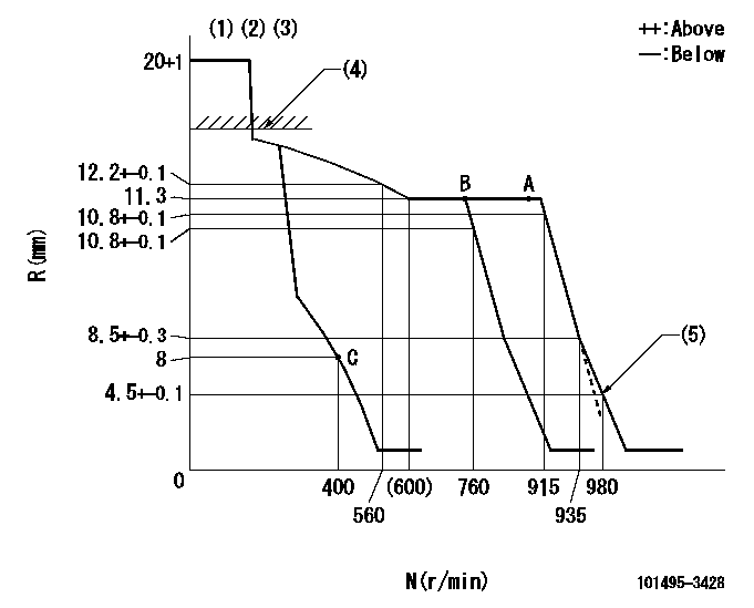
N:Pump speed
R:Rack position (mm)
(1)Target notch: K
(2)Tolerance for racks not indicated: +-0.05mm.
(3)At governor adjustment, set the stop lever at the normal position.
(4)RACK CAP: R1
(5)Set idle sub-spring
----------
K=8 R1=(17.5)mm
----------
----------
K=8 R1=(17.5)mm
----------
Speed control lever angle
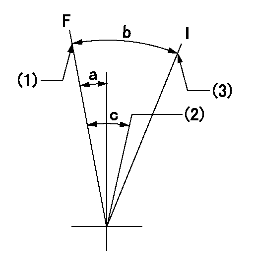
F:Full speed
I:Idle
(1)Set the pump speed at aa. ( At delivery )
(2)When pump speed set at bb
(3)Stopper bolt setting
----------
aa=915r/min bb=760r/min
----------
a=0deg+-5deg b=20.5deg+-5deg c=6deg+-5deg
----------
aa=915r/min bb=760r/min
----------
a=0deg+-5deg b=20.5deg+-5deg c=6deg+-5deg
Stop lever angle
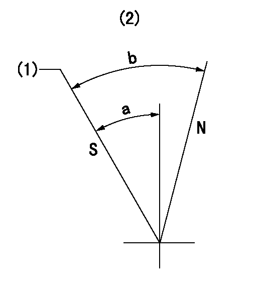
N:Pump normal
S:Stop the pump.
(1)Rack position = aa, speed = bb (stamp at delivery)
(2)No return spring
----------
aa=1-0.5mm bb=0r/min
----------
a=27.5deg+-5deg b=(55deg)
----------
aa=1-0.5mm bb=0r/min
----------
a=27.5deg+-5deg b=(55deg)
0000001501 I/P WITH LOAD PLUNGER ADJ
Load plunger-equipped pump adjustment
1. Adjust the variation between cylinders and the injection quantity.
2. At Full point A, adjust the pre-stroke to the specified value.
3. After pre-stroke adjustment, reconfirm that the fuel injection quantity and the variation between cylinders is as specified.
----------
----------
----------
----------
Timing setting
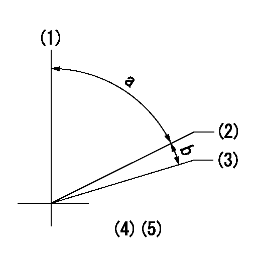
(1)Pump vertical direction
(2)Position of key groove at No 1 cylinder's beginning of injection
(3)Stamp aligning marks on the pump housing flange.
(4)After adjusting the injection quantity, adjust at rack position aa.
----------
aa=11.3mm
----------
a=58deg+-3deg b=2deg+-30min
----------
aa=11.3mm
----------
a=58deg+-3deg b=2deg+-30min
Have questions with 101495-3428?
Group cross 101495-3428 ZEXEL
Komatsu
Komatsu
101495-3428
9 400 614 531
6205711151
INJECTION-PUMP ASSEMBLY
S4D95LE-2
S4D95LE-2