
Rating:
Information injection-pump assembly
BOSCH
F 01G 09U 02A
f01g09u02a
ZEXEL
101491-9991
1014919991
Service parts 101491-9991 INJECTION-PUMP ASSEMBLY:
1.
_
6.
COUPLING PLATE
7.
COUPLING PLATE
8.
_
9.
_
11.
Nozzle and Holder
16600-0T003
12.
Open Pre:MPa(Kqf/cm2)
18.6{190}

15.
NOZZLE SET
Cross reference number
BOSCH
F 01G 09U 02A
f01g09u02a
ZEXEL
101491-9991
1014919991
Zexel num
Bosch num
Firm num
Name
Calibration Data:
Adjustment conditions
Test oil
1404 Test oil ISO4113 or {SAEJ967d}
1404 Test oil ISO4113 or {SAEJ967d}
Test oil temperature
degC
40
40
45
Nozzle and nozzle holder
105780-8140
Bosch type code
EF8511/9A
Nozzle
105780-0000
Bosch type code
DN12SD12T
Nozzle holder
105780-2080
Bosch type code
EF8511/9
Opening pressure
MPa
17.2
Opening pressure
kgf/cm2
175
Injection pipe
Outer diameter - inner diameter - length (mm) mm 6-2-600
Outer diameter - inner diameter - length (mm) mm 6-2-600
Overflow valve
131424-1520
Overflow valve opening pressure
kPa
157
123
191
Overflow valve opening pressure
kgf/cm2
1.6
1.25
1.95
Tester oil delivery pressure
kPa
157
157
157
Tester oil delivery pressure
kgf/cm2
1.6
1.6
1.6
Direction of rotation (viewed from drive side)
Right R
Right R
Injection timing adjustment
Direction of rotation (viewed from drive side)
Right R
Right R
Injection order
1-3-4-2
Pre-stroke
mm
3.2
3.15
3.25
Rack position
Point A R=A
Point A R=A
Beginning of injection position
Drive side NO.1
Drive side NO.1
Difference between angles 1
Cal 1-3 deg. 90 89.5 90.5
Cal 1-3 deg. 90 89.5 90.5
Difference between angles 2
Cal 1-4 deg. 180 179.5 180.5
Cal 1-4 deg. 180 179.5 180.5
Difference between angles 3
Cyl.1-2 deg. 270 269.5 270.5
Cyl.1-2 deg. 270 269.5 270.5
Injection quantity adjustment
Adjusting point
-
Rack position
12.7
Pump speed
r/min
1000
1000
1000
Average injection quantity
mm3/st.
73.1
71.5
74.7
Max. variation between cylinders
%
0
-2.5
2.5
Basic
*
Fixing the rack
*
Standard for adjustment of the maximum variation between cylinders
*
Injection quantity adjustment_02
Adjusting point
H
Rack position
9.5+-0.5
Pump speed
r/min
300
300
300
Average injection quantity
mm3/st.
9
7.2
10.8
Max. variation between cylinders
%
0
-15
15
Fixing the rack
*
Standard for adjustment of the maximum variation between cylinders
*
Injection quantity adjustment_03
Adjusting point
A
Rack position
R1(12.7)
Pump speed
r/min
1000
1000
1000
Average injection quantity
mm3/st.
73.1
72.1
74.1
Basic
*
Fixing the lever
*
Injection quantity adjustment_04
Adjusting point
B
Rack position
R1-0.1
Pump speed
r/min
1600
1600
1600
Average injection quantity
mm3/st.
79.9
75.9
83.9
Fixing the lever
*
Injection quantity adjustment_05
Adjusting point
I
Rack position
-
Pump speed
r/min
100
100
100
Average injection quantity
mm3/st.
109
93
125
Fixing the lever
*
Timer adjustment
Pump speed
r/min
1010--
Advance angle
deg.
0
0
0
Remarks
Start
Start
Timer adjustment_02
Pump speed
r/min
960
Advance angle
deg.
0.3
Timer adjustment_03
Pump speed
r/min
(1030)
Advance angle
deg.
0.8
0.5
1.1
Remarks
Measure the actual speed.
Measure the actual speed.
Timer adjustment_04
Pump speed
r/min
-
Advance angle
deg.
0.8
0.5
1.1
Remarks
Measure the actual speed.
Measure the actual speed.
Timer adjustment_05
Pump speed
r/min
1600
Advance angle
deg.
5
4.5
5.5
Remarks
Finish
Finish
Test data Ex:
Governor adjustment
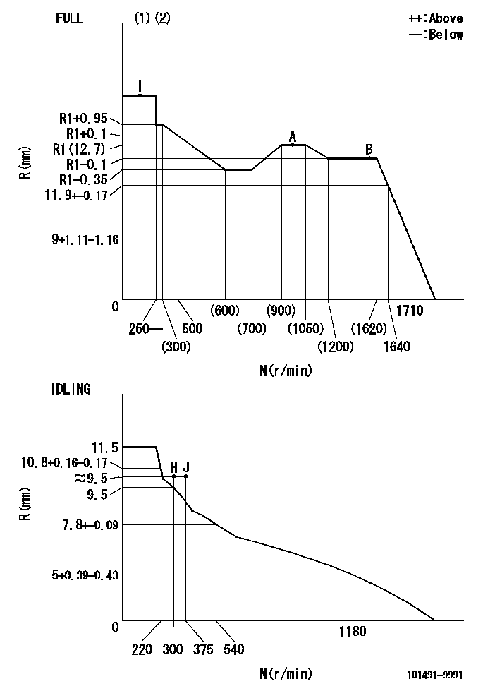
N:Pump speed
R:Rack position (mm)
(1)Torque cam stamping: T1
(2)Tolerance for racks not indicated: +-0.05mm.
----------
T1=H20
----------
----------
T1=H20
----------
Speed control lever angle
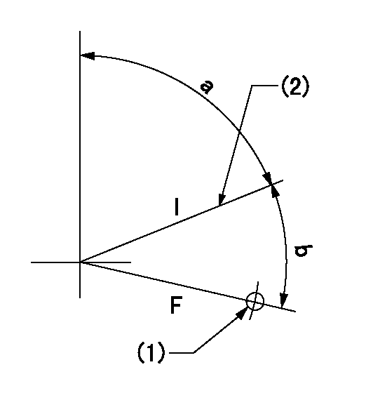
F:Full speed
I:Idle
(1)Use the hole at R = aa
(2)Stopper bolt set position 'H'
----------
aa=32mm
----------
a=70deg+-5deg b=(40deg)+-3deg
----------
aa=32mm
----------
a=70deg+-5deg b=(40deg)+-3deg
Stop lever angle
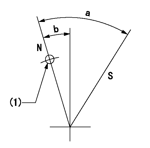
N:Pump normal
S:Stop the pump.
(1)Use the pin at R = aa
----------
aa=12mm
----------
a=29deg+-5deg b=10deg+-5deg
----------
aa=12mm
----------
a=29deg+-5deg b=10deg+-5deg
0000001501 LEVER
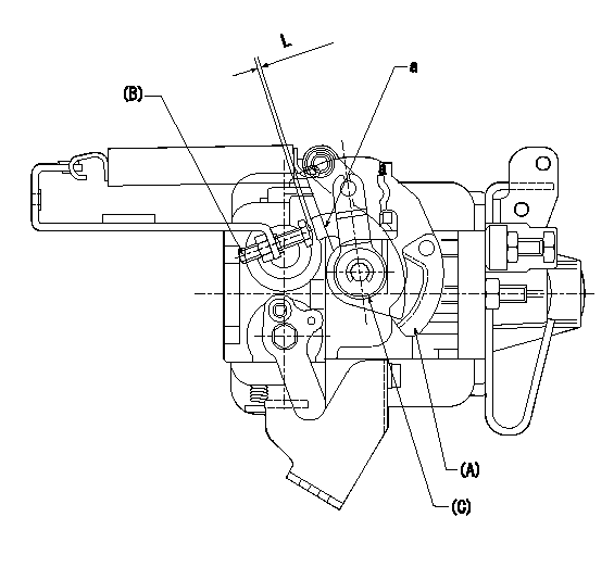
(A) Speed lever (lower)
(B) Stopper bolt
(C) Special lever (upper)
a:Point A (inside lever)
1. Special lever adjustment
(1)With the speed lever at the idle position, set the accelerator lever stopper bolt so that the accelerator lever contacts the speed lever at point a.
(2)Back off the stopper bolt L and set.
----------
L=1+0.5mm
----------
----------
L=1+0.5mm
----------
Timing setting

(1)Pump vertical direction
(2)Position of gear's standard threaded hole (position of gear mark 'S') at No 1 cylinder's beginning of injection
(3)B.T.D.C.: aa
(4)-
----------
aa=11deg
----------
a=(60deg)
----------
aa=11deg
----------
a=(60deg)