Rating:
Information injection-pump assembly
BOSCH
9 400 619 547
9400619547
ZEXEL
101491-9065
1014919065
Service parts 101491-9065 INJECTION-PUMP ASSEMBLY:
1.
_
4.
SUPPLY PUMP
6.
COUPLING PLATE
7.
COUPLING PLATE
8.
_
9.
_
11.
Nozzle and Holder
SL0113640A
12.
Open Pre:MPa(Kqf/cm2)
16.7{170}
15.
NOZZLE SET
Cross reference number
BOSCH
9 400 619 547
9400619547
ZEXEL
101491-9065
1014919065
Zexel num
Bosch num
Firm num
Name
Calibration Data:
Adjustment conditions
Test oil
1404 Test oil ISO4113 or {SAEJ967d}
1404 Test oil ISO4113 or {SAEJ967d}
Test oil temperature
degC
40
40
45
Nozzle and nozzle holder
105780-8140
Bosch type code
EF8511/9A
Nozzle
105780-0000
Bosch type code
DN12SD12T
Nozzle holder
105780-2080
Bosch type code
EF8511/9
Opening pressure
MPa
17.2
Opening pressure
kgf/cm2
175
Injection pipe
Outer diameter - inner diameter - length (mm) mm 6-2-600
Outer diameter - inner diameter - length (mm) mm 6-2-600
Overflow valve opening pressure
kPa
157
123
191
Overflow valve opening pressure
kgf/cm2
1.6
1.25
1.95
Tester oil delivery pressure
kPa
157
157
157
Tester oil delivery pressure
kgf/cm2
1.6
1.6
1.6
Direction of rotation (viewed from drive side)
Right R
Right R
Injection timing adjustment
Direction of rotation (viewed from drive side)
Right R
Right R
Injection order
1-3-4-2
Pre-stroke
mm
3.4
3.35
3.45
Beginning of injection position
Drive side NO.1
Drive side NO.1
Difference between angles 1
Cal 1-3 deg. 90 89.5 90.5
Cal 1-3 deg. 90 89.5 90.5
Difference between angles 2
Cal 1-4 deg. 180 179.5 180.5
Cal 1-4 deg. 180 179.5 180.5
Difference between angles 3
Cyl.1-2 deg. 270 269.5 270.5
Cyl.1-2 deg. 270 269.5 270.5
Injection quantity adjustment
Adjusting point
-
Rack position
11.21+-0
.02
Pump speed
r/min
1000
1000
1000
Average injection quantity
mm3/st.
56.8
56.3
57.3
Max. variation between cylinders
%
0
-2.5
2.5
Basic
*
Fixing the rack
*
Standard for adjustment of the maximum variation between cylinders
*
Injection quantity adjustment_02
Adjusting point
H'
Rack position
9.6+-0.5
Pump speed
r/min
325
325
325
Average injection quantity
mm3/st.
9
7
11
Max. variation between cylinders
%
0
-14
14
Fixing the rack
*
Standard for adjustment of the maximum variation between cylinders
*
Injection quantity adjustment_03
Adjusting point
A
Rack position
11.21+-0
.5
Pump speed
r/min
1000
1000
1000
Average injection quantity
mm3/st.
56.8
56.3
57.3
Basic
*
Fixing the lever
*
Injection quantity adjustment_04
Adjusting point
B
Rack position
11.48+-0
.5
Pump speed
r/min
1700
1700
1700
Average injection quantity
mm3/st.
68.9
66.9
70.9
Fixing the lever
*
Injection quantity adjustment_05
Adjusting point
C
Rack position
11.32+-0
.5
Pump speed
r/min
625
625
625
Average injection quantity
mm3/st.
42
40
44
Fixing the lever
*
Injection quantity adjustment_06
Adjusting point
I
Rack position
16.3+-0.
5
Pump speed
r/min
100
100
100
Average injection quantity
mm3/st.
91
81
96
Fixing the lever
*
Rack limit
*
Injection quantity adjustment_07
Adjusting point
H
Rack position
9.3+-0.5
Pump speed
r/min
325
325
325
Average injection quantity
mm3/st.
7
6.5
7.5
Fixing the lever
*
Timer adjustment
Pump speed
r/min
1350+-25
Advance angle
deg.
0
0
0
Remarks
Start
Start
Timer adjustment_02
Pump speed
r/min
1700
Advance angle
deg.
3.5
3.2
3.8
Remarks
Finish
Finish
Test data Ex:
Governor adjustment
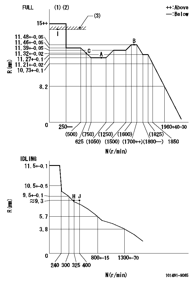
N:Pump speed
R:Rack position (mm)
(1)Torque cam stamping: T1
(2)Tolerance for racks not indicated: R1, speed N1
(3)RACK LIMIT
----------
T1=C83 R1=+-0.02mm N1=+-3r/min
----------
----------
T1=C83 R1=+-0.02mm N1=+-3r/min
----------
Speed control lever angle
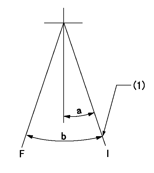
F:Full speed
I:Idle
(1)Set the stopper bolt (rack position = aa, speed = bb).
----------
aa=(9.3)mm bb=325r/min
----------
a=20deg+-5deg b=41deg+-3deg
----------
aa=(9.3)mm bb=325r/min
----------
a=20deg+-5deg b=41deg+-3deg
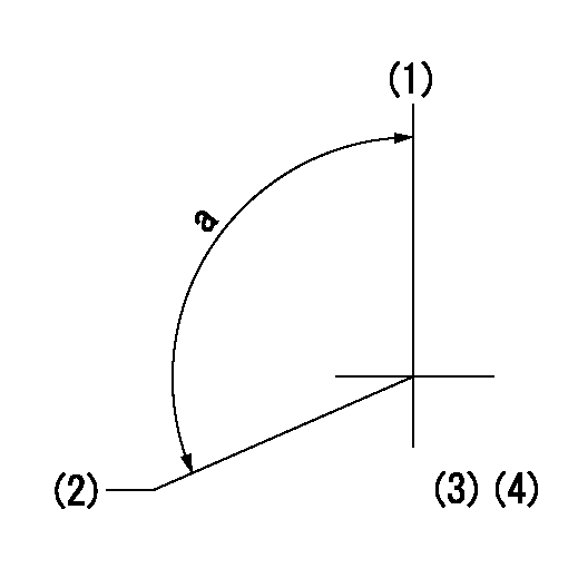
Stop lever angle
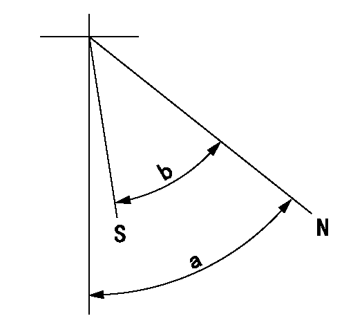
N:Pump normal
S:Stop the pump.
----------
----------
a=40deg+-5deg b=40deg+-5deg
----------
----------
a=40deg+-5deg b=40deg+-5deg
0000001501 GOV RACK POSITION CONFIRM
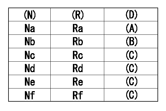
Confirm the governor adjustment rack position.
Standard point A
Set the torque cam B.
(C) Confirmation
(D) Remarks
(N): Speed of the pump
(R) Rack position (mm)
----------
----------
Na=1000r/min Nb=625r/min Nc=1800r/min Nd=1700r/min Ne=1400r/min Nf=450r/min Ra=11.21+-0.02mm Rb=11.32+-0.02mm Rc=11.27+-0.1mm Rd=11.48+-0.05mm Re=11.39+-0.05mm Rf=11.46+-0.05mm
----------
----------
Na=1000r/min Nb=625r/min Nc=1800r/min Nd=1700r/min Ne=1400r/min Nf=450r/min Ra=11.21+-0.02mm Rb=11.32+-0.02mm Rc=11.27+-0.1mm Rd=11.48+-0.05mm Re=11.39+-0.05mm Rf=11.46+-0.05mm
0000001601 ACS
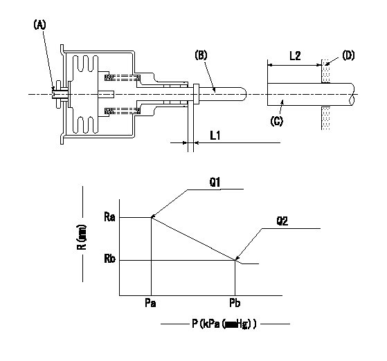
(A) Set screw
(B) Push rod 1
(C) Push rod 2
(D) Cover
1. Aneroid compensator unit adjustment
(1)Select the push rod 2 to obtain L2.
(2)Screw in (A) to obtain L1.
2. Adjustment when mounting the governor.
(1)Set the speed of the pump to N1 r/min and fix the control lever at the full set position.
(2)Screw in the aneroid compensator to obtain the performance shown in the graph above.
(3)As there is hysterisis, measure when the absolute pressure drops.
(4)Hysterisis must not exceed rack position = h1.
----------
N1=1000r/min L1=(1.5) mm L2=11+-0.5mm h1=-
----------
Ra=(11.21)mm Rb=(10.8)mm Pa=88.6+-2.7kPa(665+-20mmHg) Pb=79.4+-0.7kPa(596+-5mmHg) Q1=56.8+-0.5cm3/1000st Q2=48.8+-1cm3/1000st
----------
N1=1000r/min L1=(1.5) mm L2=11+-0.5mm h1=-
----------
Ra=(11.21)mm Rb=(10.8)mm Pa=88.6+-2.7kPa(665+-20mmHg) Pb=79.4+-0.7kPa(596+-5mmHg) Q1=56.8+-0.5cm3/1000st Q2=48.8+-1cm3/1000st
Timing setting
(1)Pump vertical direction
(2)Position of gear mark 'CC' at No 1 cylinder's beginning of injection
(3)B.T.D.C.: aa
(4)-
----------
aa=12.5deg
----------
a=(130deg)
----------
aa=12.5deg
----------
a=(130deg)