Rating:
Information injection-pump assembly
BOSCH
9 400 613 253
9400613253
ZEXEL
101405-3310
1014053310
KOMATSU
4063772
4063772
Compare Prices: .
As an associate, we earn commssions on qualifying purchases through the links below

10-32 Nylon Insert Hex Lock Nuts, Solid Brass, Grade 360, Plain Finish, Quantity 1000 by Fastenere
Fastenere Lock nuts provide a distinct advantage over a lock washer when the bolt or threaded stud is subject to vibration the inserts inner diameter is bit smaller than the entire diameter of the screw thereby locking the fastener in place by gripping the nylon firmly around the bolt when fastened. || Nylon insert lock nuts provide a locking mechanism that resists vibrations and torque that could cause loosening and a failure of the fastened parts the nylon insert conforms to the threads of the screw on which it is placed. This causes the nylon lock nut to grip better against the threads and reduces the chances of the nut loosening due to the vibration of the screw. || External hex drives can be turned with an adjustable wrench, combination wrench and 6- or 12-point sockets and offers high torque transfer. || Fastenere brass fasteners are cleaned and applied with a sealer that brings out the bright yellow brass finish and helps to maintain it. || Made of Grade 360 Brass, known for its strength and resistance to corrosion with properties closely resembling that of steel and offering the highest machinability of all copper alloys.
Fastenere Lock nuts provide a distinct advantage over a lock washer when the bolt or threaded stud is subject to vibration the inserts inner diameter is bit smaller than the entire diameter of the screw thereby locking the fastener in place by gripping the nylon firmly around the bolt when fastened. || Nylon insert lock nuts provide a locking mechanism that resists vibrations and torque that could cause loosening and a failure of the fastened parts the nylon insert conforms to the threads of the screw on which it is placed. This causes the nylon lock nut to grip better against the threads and reduces the chances of the nut loosening due to the vibration of the screw. || External hex drives can be turned with an adjustable wrench, combination wrench and 6- or 12-point sockets and offers high torque transfer. || Fastenere brass fasteners are cleaned and applied with a sealer that brings out the bright yellow brass finish and helps to maintain it. || Made of Grade 360 Brass, known for its strength and resistance to corrosion with properties closely resembling that of steel and offering the highest machinability of all copper alloys.
Service parts 101405-3310 INJECTION-PUMP ASSEMBLY:
1.
_

5.
AUTOM. ADVANCE MECHANIS
6.
COUPLING PLATE
7.
COUPLING PLATE
8.
_
9.
_
11.
Nozzle and Holder
4063212
12.
Open Pre:MPa(Kqf/cm2)
22.0{224}

15.
NOZZLE SET
Cross reference number
BOSCH
9 400 613 253
9400613253
ZEXEL
101405-3310
1014053310
KOMATSU
4063772
4063772
Zexel num
Bosch num
Firm num
Name
101405-3310
9 400 613 253
4063772 KOMATSU
INJECTION-PUMP ASSEMBLY
SAA4D102E K 14BC INJECTION PUMP ASSY PE4A,5A, PE
SAA4D102E K 14BC INJECTION PUMP ASSY PE4A,5A, PE
101405-3310
9 400 613 253
6737711230 KOMATSU
INJECTION-PUMP ASSEMBLY
SAA4D102E K 14BC INJECTION PUMP ASSY PE4A,5A, PE
SAA4D102E K 14BC INJECTION PUMP ASSY PE4A,5A, PE
Calibration Data:
Adjustment conditions
Test oil
1404 Test oil ISO4113 or {SAEJ967d}
1404 Test oil ISO4113 or {SAEJ967d}
Test oil temperature
degC
40
40
45
Nozzle and nozzle holder
105780-8140
Bosch type code
EF8511/9A
Nozzle
105780-0000
Bosch type code
DN12SD12T
Nozzle holder
105780-2080
Bosch type code
EF8511/9
Opening pressure
MPa
17.2
Opening pressure
kgf/cm2
175
Injection pipe
Outer diameter - inner diameter - length (mm) mm 6-2-600
Outer diameter - inner diameter - length (mm) mm 6-2-600
Overflow valve
131424-3420
Overflow valve opening pressure
kPa
255
221
289
Overflow valve opening pressure
kgf/cm2
2.6
2.25
2.95
Tester oil delivery pressure
kPa
255
255
255
Tester oil delivery pressure
kgf/cm2
2.6
2.6
2.6
Direction of rotation (viewed from drive side)
Right R
Right R
Injection timing adjustment
Direction of rotation (viewed from drive side)
Right R
Right R
Injection order
1-3-4-2
Pre-stroke
mm
2.7
2.65
2.75
Rack position
After adjusting injection quantity. R=A
After adjusting injection quantity. R=A
Beginning of injection position
Drive side NO.1
Drive side NO.1
Difference between angles 1
Cal 1-3 deg. 90 89.5 90.5
Cal 1-3 deg. 90 89.5 90.5
Difference between angles 2
Cal 1-4 deg. 180 179.5 180.5
Cal 1-4 deg. 180 179.5 180.5
Difference between angles 3
Cyl.1-2 deg. 270 269.5 270.5
Cyl.1-2 deg. 270 269.5 270.5
Injection quantity adjustment
Adjusting point
A
Rack position
9.2
Pump speed
r/min
1100
1100
1100
Average injection quantity
mm3/st.
93.5
92.5
94.5
Max. variation between cylinders
%
0
-2.5
2.5
Basic
*
Fixing the lever
*
Boost pressure
kPa
45.3
45.3
Boost pressure
mmHg
340
340
Hydraulic cylinder ON
*
Injection quantity adjustment_02
Adjusting point
-
Rack position
6.4+-0.5
Pump speed
r/min
485
485
485
Average injection quantity
mm3/st.
10
9
11
Max. variation between cylinders
%
0
-15
15
Fixing the rack
*
Boost pressure
kPa
0
0
0
Boost pressure
mmHg
0
0
0
Hydraulic cylinder ON
*
Remarks
Adjust only variation between cylinders; adjust governor according to governor specifications.
Adjust only variation between cylinders; adjust governor according to governor specifications.
Injection quantity adjustment_03
Adjusting point
E
Rack position
9.4++
Pump speed
r/min
100
100
100
Average injection quantity
mm3/st.
65
60
70
Fixing the lever
*
Boost pressure
kPa
0
0
0
Boost pressure
mmHg
0
0
0
Hydraulic cylinder OFF
*
Rack limit
*
Boost compensator adjustment
Pump speed
r/min
650
650
650
Rack position
R1-1
Boost pressure
kPa
10.7
8
13.4
Boost pressure
mmHg
80
60
100
Boost compensator adjustment_02
Pump speed
r/min
650
650
650
Rack position
R1-0.4
Boost pressure
kPa
20
18.7
21.3
Boost pressure
mmHg
150
140
160
Boost compensator adjustment_03
Pump speed
r/min
650
650
650
Rack position
R1(9.2)
Boost pressure
kPa
32
32
32
Boost pressure
mmHg
240
240
240
Test data Ex:
Governor adjustment
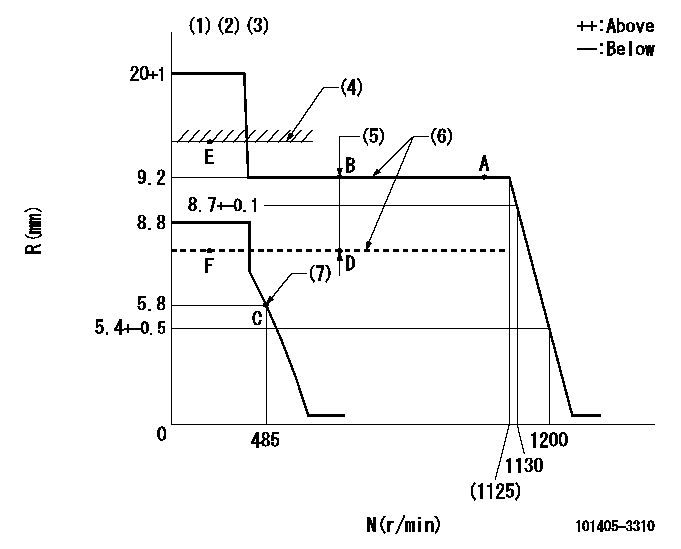
N:Pump speed
R:Rack position (mm)
(1)Target notch: K
(2)Tolerance for racks not indicated: +-0.05mm.
(3)Deliver without the torque control spring operating.
(4)RACK LIMIT (When hydraulic cylinder is OFF)
(5)Boost compensator stroke: BCL
(6)When hydraulic cylinder ON: P1
(7)Set idle sub-spring
----------
K=14 BCL=1+-0.1mm P1=(127+-10kPa{1.3+-0.1kgf/cm2})
----------
----------
K=14 BCL=1+-0.1mm P1=(127+-10kPa{1.3+-0.1kgf/cm2})
----------
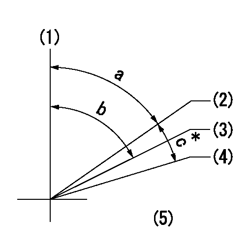
Speed control lever angle
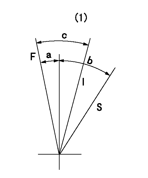
F:Full speed
I:Idle
S:Stop
(1)Use the center hole at R = aa
----------
aa=80mm
----------
a=16deg+-5deg b=32deg+-3deg c=35deg+-5deg
----------
aa=80mm
----------
a=16deg+-5deg b=32deg+-3deg c=35deg+-5deg
0000001501 TAMPER PROOF
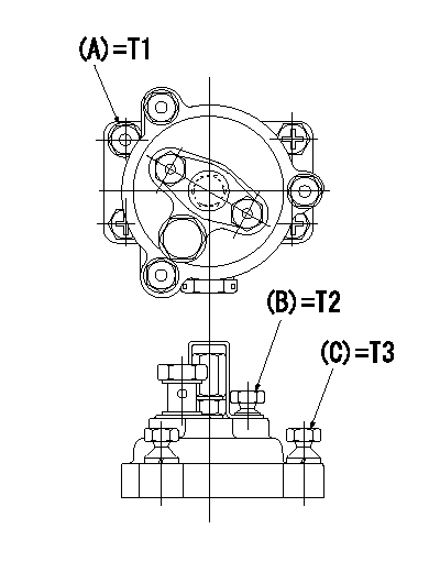
Tamperproofing-equipped boost compensator cover installation procedure
(1)After adjusting the governor and the boost compensator, tighten to the specified torque to break off the bolt heads.
(Tightening torque T = T1 maximum)
(2)After adjusting the governor and the boost compensator, tighten to the specified torque to break off the bolt heads.
(Tightening torque T = T2)
(3)After adjusting the governor and the boost compensator, tighten to the specified torque to break off the bolt heads.
(Tightening torque T = T3)
----------
T1=7.16~9.12N-m(0.73~0.93kgf-m) T2=2.9~4.4N-m(0.3~0.45kgf-m) T3=2.9~4.4N-m(0.3~0.45kgf-m)
----------
----------
T1=7.16~9.12N-m(0.73~0.93kgf-m) T2=2.9~4.4N-m(0.3~0.45kgf-m) T3=2.9~4.4N-m(0.3~0.45kgf-m)
----------
0000001601 I/P WITH LOAD PLUNGER ADJ
Adjusting procedure for load plunger equipped pump with RSV (cam lock) governor (see service information S.I. 434 for details).
At cam lift h+-0.01, set the camshaft c deg from the * mark in accordance with the timing adjustment procedure.
2. Align the flyweight's timing tooth position and the lock pin groove and then fully tighten the flyweight to the camshaft. Then, remove the lock pin.
3. Adjust the maximum variation between cylinders and injection quantity.
4. Adjust using the pre-stroke adjusting shim so that the pre-stroke value is the value for 4/4 load (standard point A).
5. After adjusting the pre-stroke, reconfirm that the injection quantity and the maximum variation between cylinders are as specified.
6. At delivery, again fix the flyweight using the lock pin.
----------
h=2.7+-0.01mm c=5deg45min+-30min
----------
----------
h=2.7+-0.01mm c=5deg45min+-30min
----------
Timing setting
(1)Pump vertical direction
(2)Key groove position for No. 1 cylinder's cam lift h = cc (at BTDC aa).
(3)Key groove position for No. 1 cylinder's beginning of injection (at point A after injection quantity adjustment).
(4)Position of the key groove of the No. 1 cylinder at B.T.D.C. bb (fix the governor flyweight at this position for delivery).
(5)B.T.D.C.: aa
----------
aa=11.5deg bb=0deg cc=2.7+-0.01mm
----------
a=55deg48min+-3deg b=55deg48min+-3deg13min48sec c=5deg45min+-30min
----------
aa=11.5deg bb=0deg cc=2.7+-0.01mm
----------
a=55deg48min+-3deg b=55deg48min+-3deg13min48sec c=5deg45min+-30min
Have questions with 101405-3310?
Group cross 101405-3310 ZEXEL
Komatsu
101405-3310
9 400 613 253
4063772
INJECTION-PUMP ASSEMBLY
SAA4D102E
SAA4D102E
101405-3310
9 400 613 253
6737711230
INJECTION-PUMP ASSEMBLY
SAA4D102E
SAA4D102E