
Rating:
Information injection-pump assembly
BOSCH
9 400 614 039
9400614039
ZEXEL
101403-9200
1014039200
NISSAN-DIESEL
1670033D01
1670033d01
Include in #1:
101605-9433
as _
Cross reference number
BOSCH
9 400 614 039
9400614039
ZEXEL
101403-9200
1014039200
NISSAN-DIESEL
1670033D01
1670033d01
Zexel num
Bosch num
Firm num
Name
Calibration Data:
Adjustment conditions
Test oil
1404 Test oil ISO4113 or {SAEJ967d}
1404 Test oil ISO4113 or {SAEJ967d}
Test oil temperature
degC
40
40
45
Nozzle and nozzle holder
105780-8140
Bosch type code
EF8511/9A
Nozzle
105780-0000
Bosch type code
DN12SD12T
Nozzle holder
105780-2080
Bosch type code
EF8511/9
Opening pressure
MPa
17.2
Opening pressure
kgf/cm2
175
Injection pipe
Outer diameter - inner diameter - length (mm) mm 6-2-600
Outer diameter - inner diameter - length (mm) mm 6-2-600
Overflow valve
134424-4120
Overflow valve opening pressure
kPa
255
221
289
Overflow valve opening pressure
kgf/cm2
2.6
2.25
2.95
Tester oil delivery pressure
kPa
255
255
255
Tester oil delivery pressure
kgf/cm2
2.6
2.6
2.6
Direction of rotation (viewed from drive side)
Right R
Right R
Injection timing adjustment
Direction of rotation (viewed from drive side)
Right R
Right R
Injection order
1-3-4-2
Pre-stroke
mm
3.2
3.15
3.25
Rack position
Point A R=A
Point A R=A
Beginning of injection position
Drive side NO.1
Drive side NO.1
Difference between angles 1
Cal 1-3 deg. 90 89.5 90.5
Cal 1-3 deg. 90 89.5 90.5
Difference between angles 2
Cal 1-4 deg. 180 179.5 180.5
Cal 1-4 deg. 180 179.5 180.5
Difference between angles 3
Cyl.1-2 deg. 270 269.5 270.5
Cyl.1-2 deg. 270 269.5 270.5
Injection quantity adjustment
Adjusting point
-
Rack position
13.4
Pump speed
r/min
900
900
900
Average injection quantity
mm3/st.
88.5
86.9
90.1
Max. variation between cylinders
%
0
-3.5
3.5
Basic
*
Fixing the rack
*
Standard for adjustment of the maximum variation between cylinders
*
Injection quantity adjustment_02
Adjusting point
H
Rack position
9.7+-0.5
Pump speed
r/min
325
325
325
Average injection quantity
mm3/st.
12
10.2
13.8
Max. variation between cylinders
%
0
-10
10
Fixing the rack
*
Standard for adjustment of the maximum variation between cylinders
*
Injection quantity adjustment_03
Adjusting point
A
Rack position
R1(13.4)
Pump speed
r/min
900
900
900
Average injection quantity
mm3/st.
88.5
87.5
89.5
Basic
*
Fixing the lever
*
Boost pressure
kPa
64
64
Boost pressure
mmHg
480
480
Injection quantity adjustment_04
Adjusting point
B
Rack position
R1+0.45
Pump speed
r/min
1550
1550
1550
Average injection quantity
mm3/st.
91.5
87.5
95.5
Fixing the lever
*
Boost pressure
kPa
64
64
Boost pressure
mmHg
480
480
Boost compensator adjustment
Pump speed
r/min
500
500
500
Rack position
R2-1.05
Boost pressure
kPa
14.7
13.4
16
Boost pressure
mmHg
110
100
120
Boost compensator adjustment_02
Pump speed
r/min
500
500
500
Rack position
R2(R1-0.
2)
Boost pressure
kPa
50.7
50.7
50.7
Boost pressure
mmHg
380
380
380
Timer adjustment
Pump speed
r/min
(N1+50)-
-
Advance angle
deg.
0
0
0
Remarks
Start
Start
Timer adjustment_02
Pump speed
r/min
N1
Advance angle
deg.
0.5
Remarks
Measure the actual speed.
Measure the actual speed.
Timer adjustment_03
Pump speed
r/min
1550
Remarks
Measure the actual advance angle.
Measure the actual advance angle.
Timer adjustment_04
Pump speed
r/min
-
Advance angle
deg.
7
6.5
7.5
Remarks
Measure the actual speed, stop
Measure the actual speed, stop
Test data Ex:
Governor adjustment
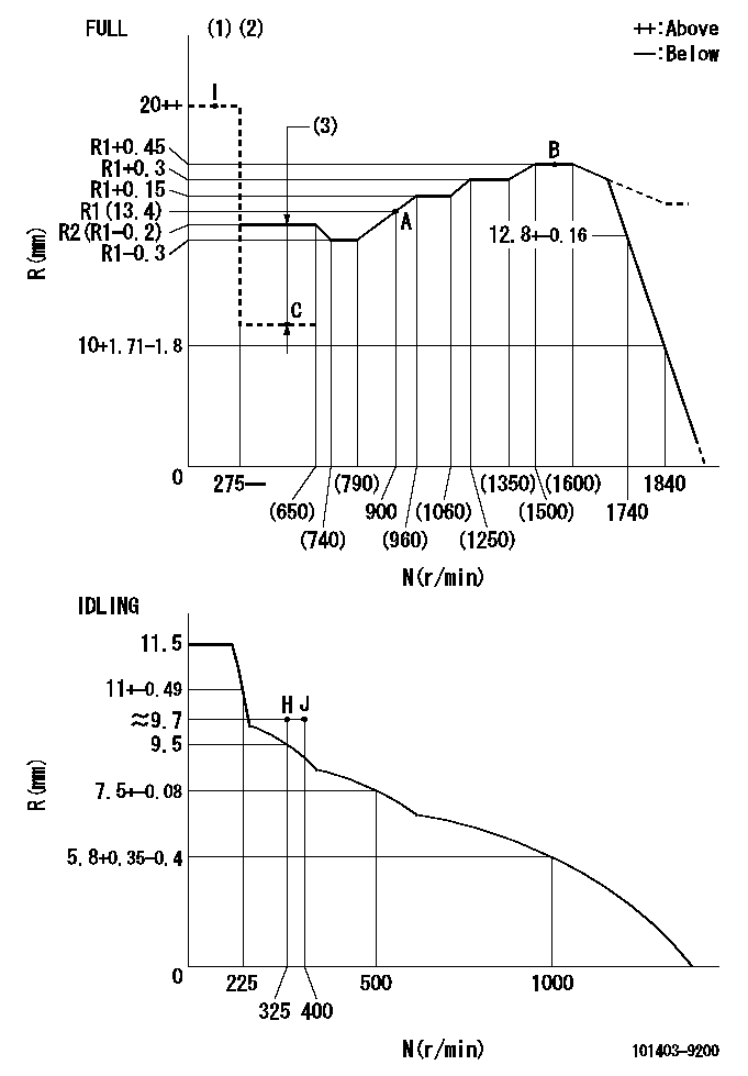
N:Pump speed
R:Rack position (mm)
(1)Torque cam stamping: T1
(2)Tolerance for racks not indicated: +-0.05mm.
(3)Boost compensator stroke: BCL
----------
T1=P14 BCL=1.05+-0.1mm
----------
----------
T1=P14 BCL=1.05+-0.1mm
----------
Speed control lever angle
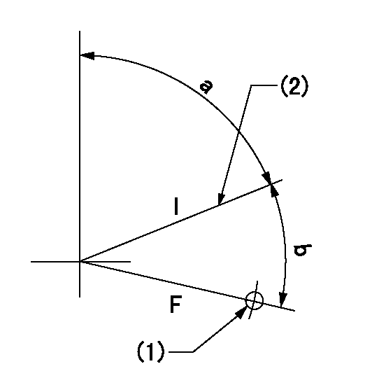
F:Full speed
I:Idle
(1)Use the hole at R = aa
(2)Stopper bolt set position 'H'
----------
aa=32mm
----------
a=71deg+-5deg b=40deg+-3deg
----------
aa=32mm
----------
a=71deg+-5deg b=40deg+-3deg
Stop lever angle
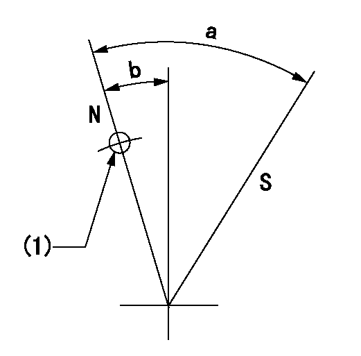
N:Pump normal
S:Stop the pump.
(1)Use the pin at R = aa
----------
aa=15mm
----------
a=29deg+-5deg b=10deg+-5deg
----------
aa=15mm
----------
a=29deg+-5deg b=10deg+-5deg
0000001501 ACS
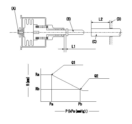
(A) Set screw
(B) Push rod 1
(C) Push rod 2
(D) Cover
1. Aneroid compensator unit adjustment
(1)Select the push rod 2 to obtain L2.
(2)Screw in (A) to obtain L1.
2. Adjustment when mounting the governor.
(1)Set the speed of the pump to N1 r/min and fix the control lever at the full set position.
(2)Screw in the aneroid compensator to obtain the performance shown in the graph above.
(3)As there is hysterisis, measure when the absolute pressure drops.
(4)Hysterisis must not exceed rack position = h1.
----------
N1=1550r/min L1=1.5+-0.5mm L2=24+-0.5mm h1=0.15mm
----------
Ra=R3(R1+0.45)mm Rb=R3-0.25mm Pa=(89.3)+-2.7kPa((670)+-20mmHg) Pb=79.4+-0.7kPa(596+-5mmHg) Q1=(91.5)+-2cm3/1000st Q2=(86.5)+-2cm3/1000st
----------
N1=1550r/min L1=1.5+-0.5mm L2=24+-0.5mm h1=0.15mm
----------
Ra=R3(R1+0.45)mm Rb=R3-0.25mm Pa=(89.3)+-2.7kPa((670)+-20mmHg) Pb=79.4+-0.7kPa(596+-5mmHg) Q1=(91.5)+-2cm3/1000st Q2=(86.5)+-2cm3/1000st
0000001601 ACS

(A) Aneroid compensator
(B) Set screw
(C) Boost pressure inlet
(D) Rack positioning screw
(E): Aneroid compensator main body
(F) Boost compensator spring
(G): Aneroid compensator spring
(H): Adjusting notch
(I) Push rod
1. Instructions for adjusting the boost compensator with the aneroid compensator
(1)Select a pushrod to obtain L1 at full boost.
(2)Remove the aneroid compensator main body.
(3)Adjust the booster compensator stroke by turning the screw at (D.
(4)Adjust the beginning of boost compensator operation by turning the notch at (H).
(5)Install the aneroid compensator at full boost state.
(6)Turn (B)'s set screw so that the distance between the snapring and the body is L2.
(7)Screw in the aneroid compensator main body and adjust the point where it comes into play.
----------
L1=24+-0.5mm L2=1.5+-0.5mm
----------
----------
L1=24+-0.5mm L2=1.5+-0.5mm
----------
Timing setting

(1)Pump vertical direction
(2)Position of gear's standard threaded hole at No 1 cylinder's beginning of injection
(3)B.T.D.C.: aa
(4)-
----------
aa=5deg
----------
a=(50deg)
----------
aa=5deg
----------
a=(50deg)