Rating:
Information injection-pump assembly
BOSCH
F 019 Z10 325
f019z10325
ZEXEL
101402-4151
1014024151
ISUZU
8970314861
8970314861
Service parts 101402-4151 INJECTION-PUMP ASSEMBLY:
1.
_
5.
AUTOM. ADVANCE MECHANIS
6.
COUPLING PLATE
8.
_
9.
_
11.
Nozzle and Holder
8-97013-319-1
12.
Open Pre:MPa(Kqf/cm2)
18.1{185}

15.
NOZZLE SET
Cross reference number
BOSCH
F 019 Z10 325
f019z10325
ZEXEL
101402-4151
1014024151
ISUZU
8970314861
8970314861
Zexel num
Bosch num
Firm num
Name
Calibration Data:
Adjustment conditions
Test oil
1404 Test oil ISO4113 or {SAEJ967d}
1404 Test oil ISO4113 or {SAEJ967d}
Test oil temperature
degC
40
40
45
Nozzle and nozzle holder
105780-8140
Bosch type code
EF8511/9A
Nozzle
105780-0000
Bosch type code
DN12SD12T
Nozzle holder
105780-2080
Bosch type code
EF8511/9
Opening pressure
MPa
17.2
Opening pressure
kgf/cm2
175
Injection pipe
Outer diameter - inner diameter - length (mm) mm 6-2-600
Outer diameter - inner diameter - length (mm) mm 6-2-600
Overflow valve
131424-4920
Overflow valve opening pressure
kPa
127
107
147
Overflow valve opening pressure
kgf/cm2
1.3
1.1
1.5
Tester oil delivery pressure
kPa
157
157
157
Tester oil delivery pressure
kgf/cm2
1.6
1.6
1.6
Direction of rotation (viewed from drive side)
Right R
Right R
Injection timing adjustment
Direction of rotation (viewed from drive side)
Right R
Right R
Injection order
1-3-4-2
Pre-stroke
mm
3.4
3.35
3.45
Beginning of injection position
Drive side NO.1
Drive side NO.1
Difference between angles 1
Cal 1-3 deg. 90 89.5 90.5
Cal 1-3 deg. 90 89.5 90.5
Difference between angles 2
Cal 1-4 deg. 180 179.5 180.5
Cal 1-4 deg. 180 179.5 180.5
Difference between angles 3
Cyl.1-2 deg. 270 269.5 270.5
Cyl.1-2 deg. 270 269.5 270.5
Injection quantity adjustment
Adjusting point
A
Rack position
9.8
Pump speed
r/min
1250
1250
1250
Average injection quantity
mm3/st.
88.6
87.5
89.7
Max. variation between cylinders
%
0
-2
2
Basic
*
Fixing the lever
*
Injection quantity adjustment_02
Adjusting point
C
Rack position
10.4
Pump speed
r/min
500
500
500
Average injection quantity
mm3/st.
83.5
81.5
85.5
Max. variation between cylinders
%
0
-4
4
Fixing the lever
*
Injection quantity adjustment_03
Adjusting point
-
Rack position
6.7+-0.5
Pump speed
r/min
440
440
440
Average injection quantity
mm3/st.
8.8
7.4
10.2
Max. variation between cylinders
%
0
-14
14
Fixing the rack
*
Remarks
Adjust only variation between cylinders; adjust governor according to governor specifications.
Adjust only variation between cylinders; adjust governor according to governor specifications.
Test data Ex:
Governor adjustment
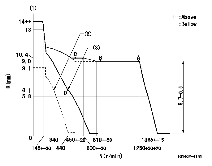
N:Pump speed
R:Rack position (mm)
(1)Target notch: K
(2)Set idle sub-spring
(3)Main spring setting
----------
K=7
----------
----------
K=7
----------
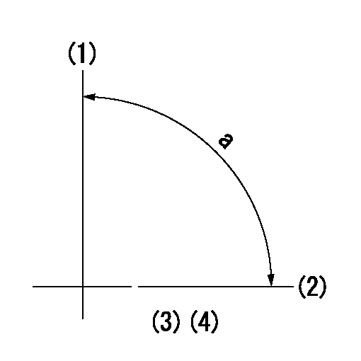
Speed control lever angle
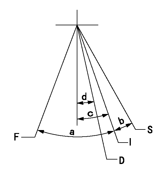
F:Full speed
I:Idle
S:Stop
D:Dead point
----------
----------
a=(23deg)+-5deg b=(16deg)+-5deg c=(16deg)+-5deg d=13deg+-3deg
----------
----------
a=(23deg)+-5deg b=(16deg)+-5deg c=(16deg)+-5deg d=13deg+-3deg
Stop lever angle
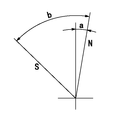
N:Pump normal
S:Stop the pump.
----------
----------
a=6deg+-5deg b=46deg+-5deg
----------
----------
a=6deg+-5deg b=46deg+-5deg
0000001501 LEVER
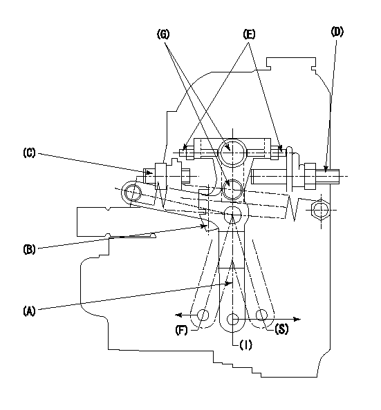
1. Variable lever adjustment
(1)Fix lever B in the idle position using the bolts C and D.
(2)Temporarily fix lever A in center of long hole.
(3)Set the dead point position temporarily and measure the lever angle.
(4)After idle adjustment, loosen the full side stopper bolt D.
(5)Move lever A in full speed direction.
(6)Fix the bolt D at the full speed position.
(7)Fix lever A using bolt E.
(8)(G) Lock using bolt.
(9)Finally, measure the lever angle and set the idle stopper bolt (C) stop position.
----------
----------
----------
----------
Timing setting
(1)Pump vertical direction
(2)Position of gear mark 'CC' at No 1 cylinder's beginning of injection
(3)B.T.D.C.: aa
(4)-
----------
aa=18deg
----------
a=(90deg)
----------
aa=18deg
----------
a=(90deg)