Rating:
Information injection-pump assembly
BOSCH
9 400 610 433
9400610433
ZEXEL
101401-9730
1014019730
NISSAN-DIESEL
1670017D11
1670017d11
Service parts 101401-9730 INJECTION-PUMP ASSEMBLY:
1.
_
6.
COUPLING PLATE
7.
COUPLING PLATE
8.
_
9.
_
11.
Nozzle and Holder
16600-17D03
12.
Open Pre:MPa(Kqf/cm2)
18.6(190)
15.
NOZZLE SET
Cross reference number
BOSCH
9 400 610 433
9400610433
ZEXEL
101401-9730
1014019730
NISSAN-DIESEL
1670017D11
1670017d11
Zexel num
Bosch num
Firm num
Name
101401-9730
9 400 610 433
1670017D11 NISSAN-DIESEL
INJECTION-PUMP ASSEMBLY
FD46 K 14BD INJECTION PUMP ASSY PE4AD PE
FD46 K 14BD INJECTION PUMP ASSY PE4AD PE
Calibration Data:
Adjustment conditions
Test oil
1404 Test oil ISO4113 or {SAEJ967d}
1404 Test oil ISO4113 or {SAEJ967d}
Test oil temperature
degC
40
40
45
Nozzle and nozzle holder
105780-8140
Bosch type code
EF8511/9A
Nozzle
105780-0000
Bosch type code
DN12SD12T
Nozzle holder
105780-2080
Bosch type code
EF8511/9
Opening pressure
MPa
17.2
Opening pressure
kgf/cm2
175
Injection pipe
Outer diameter - inner diameter - length (mm) mm 6-2-600
Outer diameter - inner diameter - length (mm) mm 6-2-600
Overflow valve
134424-4120
Overflow valve opening pressure
kPa
255
221
289
Overflow valve opening pressure
kgf/cm2
2.6
2.25
2.95
Tester oil delivery pressure
kPa
157
157
157
Tester oil delivery pressure
kgf/cm2
1.6
1.6
1.6
Direction of rotation (viewed from drive side)
Right R
Right R
Injection timing adjustment
Direction of rotation (viewed from drive side)
Right R
Right R
Injection order
1-3-4-2
Pre-stroke
mm
3.2
3.15
3.25
Rack position
Point A R=A
Point A R=A
Beginning of injection position
Drive side NO.1
Drive side NO.1
Difference between angles 1
Cal 1-3 deg. 90 89.5 90.5
Cal 1-3 deg. 90 89.5 90.5
Difference between angles 2
Cal 1-4 deg. 180 179.5 180.5
Cal 1-4 deg. 180 179.5 180.5
Difference between angles 3
Cyl.1-2 deg. 270 269.5 270.5
Cyl.1-2 deg. 270 269.5 270.5
Injection quantity adjustment
Adjusting point
-
Rack position
12.1
Pump speed
r/min
900
900
900
Average injection quantity
mm3/st.
62
60.4
63.6
Max. variation between cylinders
%
0
-3.5
3.5
Basic
*
Fixing the rack
*
Standard for adjustment of the maximum variation between cylinders
*
Injection quantity adjustment_02
Adjusting point
H
Rack position
9.5+-0.5
Pump speed
r/min
325
325
325
Average injection quantity
mm3/st.
10.5
8.7
12.3
Max. variation between cylinders
%
0
-10
10
Fixing the rack
*
Standard for adjustment of the maximum variation between cylinders
*
Injection quantity adjustment_03
Adjusting point
A
Rack position
R1(12.1)
Pump speed
r/min
900
900
900
Average injection quantity
mm3/st.
62
61
63
Basic
*
Fixing the lever
*
Injection quantity adjustment_04
Adjusting point
B
Rack position
R1+0.75
Pump speed
r/min
1450
1450
1450
Average injection quantity
mm3/st.
79
75
83
Fixing the lever
*
Injection quantity adjustment_05
Adjusting point
C
Rack position
R1-0.6
Pump speed
r/min
500
500
500
Average injection quantity
mm3/st.
49
45
53
Fixing the lever
*
Timer adjustment
Pump speed
r/min
[N1+50]-
-
Advance angle
deg.
0
0
0
Remarks
Start
Start
Timer adjustment_02
Pump speed
r/min
N1
Advance angle
deg.
0
0
0
Remarks
Measure the actual speed.
Measure the actual speed.
Timer adjustment_03
Pump speed
r/min
975
Advance angle
deg.
1
0.7
1.3
Timer adjustment_04
Pump speed
r/min
1500
Advance angle
deg.
5
4.5
5.5
Remarks
Finish
Finish
Test data Ex:
Governor adjustment
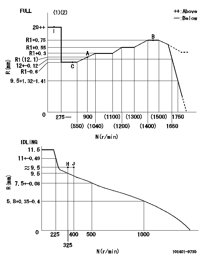
N:Pump speed
R:Rack position (mm)
(1)Torque cam stamping: T1
(2)Tolerance for racks not indicated: +-0.05mm.
----------
T1=M25
----------
----------
T1=M25
----------
Speed control lever angle
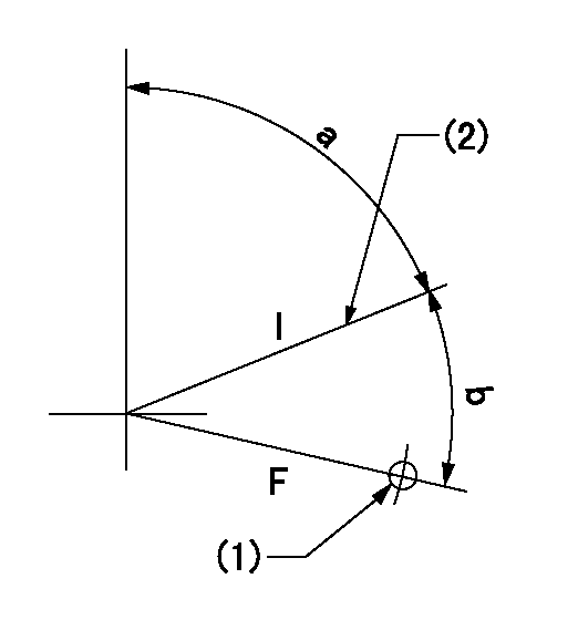
F:Full speed
I:Idle
(1)Use the hole at R = aa
(2)Stopper bolt set position 'H'
----------
aa=32mm
----------
a=70deg+-5deg b=37deg+-3deg
----------
aa=32mm
----------
a=70deg+-5deg b=37deg+-3deg
Stop lever angle
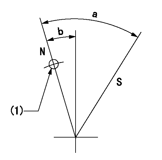
N:Normal
S:Stop
(1)Use the pin at R = aa
----------
aa=12mm
----------
a=29deg+-5deg b=10deg+-5deg
----------
aa=12mm
----------
a=29deg+-5deg b=10deg+-5deg
Timing setting

(1)Pump vertical direction
(2)Position of gear's standard threaded hole at No 1 cylinder's beginning of injection
(3)B.T.D.C.: aa
(4)-
----------
aa=8deg
----------
a=(50deg)
----------
aa=8deg
----------
a=(50deg)
Have questions with 101401-9730?
Group cross 101401-9730 ZEXEL
Mazda
Nissan-Diesel
101401-9730
9 400 610 433
1670017D11
INJECTION-PUMP ASSEMBLY
FD46
FD46