Rating:
Information injection-pump assembly
BOSCH
9 400 613 785
9400613785
ZEXEL
101401-7710
1014017710
ISUZU
8972121020
8972121020
Service parts 101401-7710 INJECTION-PUMP ASSEMBLY:
1.
_

6.
COUPLING PLATE
7.
COUPLING PLATE
8.
_
9.
_
11.
Nozzle and Holder
8-97119-811-0
12.
Open Pre:MPa(Kqf/cm2)
18.1{185}

15.
NOZZLE SET
Cross reference number
BOSCH
9 400 613 785
9400613785
ZEXEL
101401-7710
1014017710
ISUZU
8972121020
8972121020
Zexel num
Bosch num
Firm num
Name
101401-7710
9 400 613 785
8972121020 ISUZU
INJECTION-PUMP ASSEMBLY
4HG1 K 14BD INJECTION PUMP ASSY PE4AD PE
4HG1 K 14BD INJECTION PUMP ASSY PE4AD PE
Calibration Data:
Adjustment conditions
Test oil
1404 Test oil ISO4113 or {SAEJ967d}
1404 Test oil ISO4113 or {SAEJ967d}
Test oil temperature
degC
40
40
45
Nozzle and nozzle holder
105780-8140
Bosch type code
EF8511/9A
Nozzle
105780-0000
Bosch type code
DN12SD12T
Nozzle holder
105780-2080
Bosch type code
EF8511/9
Opening pressure
MPa
17.2
Opening pressure
kgf/cm2
175
Injection pipe
Outer diameter - inner diameter - length (mm) mm 6-2-600
Outer diameter - inner diameter - length (mm) mm 6-2-600
Overflow valve
134424-3920
Overflow valve opening pressure
kPa
127
107
147
Overflow valve opening pressure
kgf/cm2
1.3
1.1
1.5
Tester oil delivery pressure
kPa
157
157
157
Tester oil delivery pressure
kgf/cm2
1.6
1.6
1.6
Direction of rotation (viewed from drive side)
Left L
Left L
Injection timing adjustment
Direction of rotation (viewed from drive side)
Left L
Left L
Injection order
1-3-4-2
Pre-stroke
mm
4.1
4.05
4.15
Rack position
Point D R=D
Point D R=D
Beginning of injection position
Governor side NO.1
Governor side NO.1
Difference between angles 1
Cal 1-3 deg. 90 89.5 90.5
Cal 1-3 deg. 90 89.5 90.5
Difference between angles 2
Cal 1-4 deg. 180 179.5 180.5
Cal 1-4 deg. 180 179.5 180.5
Difference between angles 3
Cyl.1-2 deg. 270 269.5 270.5
Cyl.1-2 deg. 270 269.5 270.5
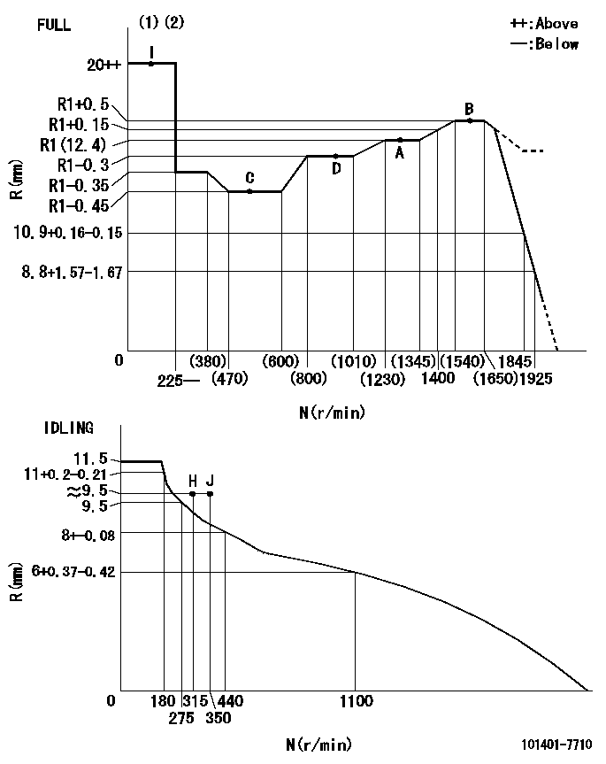
Injection quantity adjustment
Adjusting point
-
Rack position
12.4
Pump speed
r/min
1310
1310
1310
Average injection quantity
mm3/st.
73.5
71.9
75.1
Max. variation between cylinders
%
0
-4
4
Basic
*
Fixing the rack
*
Standard for adjustment of the maximum variation between cylinders
*
Injection quantity adjustment_02
Adjusting point
H
Rack position
9.5+-0.5
Pump speed
r/min
315
315
315
Average injection quantity
mm3/st.
10
8.7
11.3
Max. variation between cylinders
%
0
-10
10
Fixing the rack
*
Standard for adjustment of the maximum variation between cylinders
*
Injection quantity adjustment_03
Adjusting point
A
Rack position
R1(12.4)
Pump speed
r/min
1310
1310
1310
Average injection quantity
mm3/st.
73.5
72.5
74.5
Basic
*
Fixing the lever
*
Injection quantity adjustment_04
Adjusting point
B
Rack position
R1+0.5
Pump speed
r/min
1600
1600
1600
Average injection quantity
mm3/st.
87.5
83.5
91.5
Fixing the lever
*
Injection quantity adjustment_05
Adjusting point
C
Rack position
R1-0.45
Pump speed
r/min
520
520
520
Average injection quantity
mm3/st.
45.6
41.6
49.6
Fixing the lever
*
Injection quantity adjustment_06
Adjusting point
D
Rack position
R1-0.3
Pump speed
r/min
960
960
960
Average injection quantity
mm3/st.
61.5
57.5
65.5
Fixing the lever
*
Timer adjustment
Pump speed
r/min
-
Advance angle
deg.
0
0
0
Remarks
Measure speed (beginning of operation).
Measure speed (beginning of operation).
Timer adjustment_02
Pump speed
r/min
-
Advance angle
deg.
4.8
4.3
5.3
Remarks
Measure the actual speed.
Measure the actual speed.
Timer adjustment_03
Pump speed
r/min
-
Advance angle
deg.
5
4.5
5.5
Remarks
Measure the actual speed, stop
Measure the actual speed, stop
Test data Ex:
Governor adjustment
N:Pump speed
R:Rack position (mm)
(1)Torque cam stamping: T1
(2)Tolerance for racks not indicated: +-0.05mm.
----------
T1=M40
----------
----------
T1=M40
----------
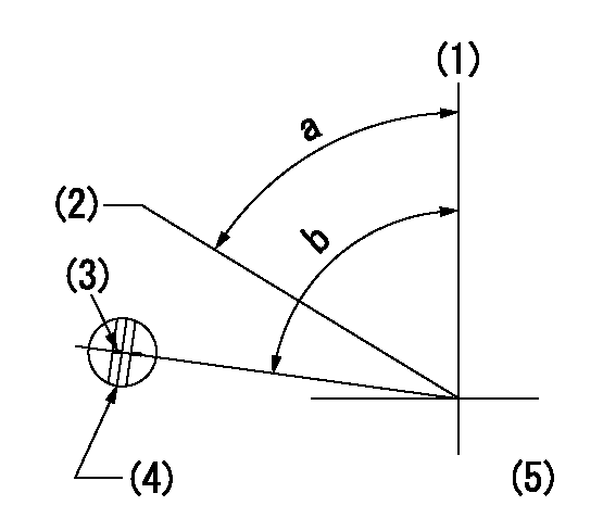
Speed control lever angle
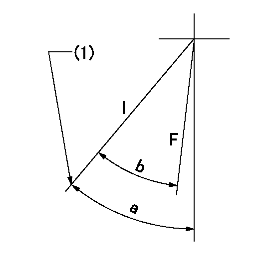
F:Full speed
I:Idle
(1)Stopper bolt set position 'H'
----------
----------
a=38deg+-5deg b=37deg+-3deg
----------
----------
a=38deg+-5deg b=37deg+-3deg
Stop lever angle
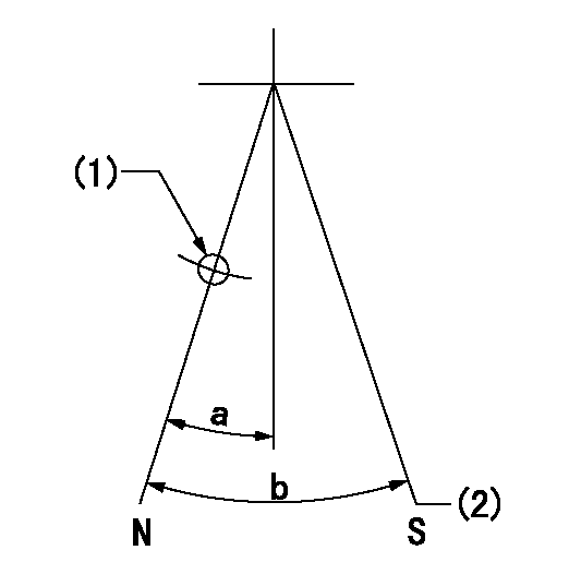
N:Pump normal
S:Stop the pump.
(1)Use the hole at R = aa
(2)At pump speed bb and rack position cc, set the stopper bolt.
----------
aa=58mm bb=1600r/min cc=5+-0.2mm
----------
a=23deg+-5deg b=(29deg)+-5deg
----------
aa=58mm bb=1600r/min cc=5+-0.2mm
----------
a=23deg+-5deg b=(29deg)+-5deg
Timing setting
(1)Pump vertical direction
(2)Position of gear's standard threaded hole at No 1 cylinder's beginning of injection
(3)Stamping position on the A/T outer rim
(4)At the No 1 cylinder's beginning of injection, align with the aligning mark seen through the bracket's check hole and mark the A/T's bevel C1.
(5)B.T.D.C.: aa
----------
aa=7deg
----------
a=(60deg) b=(85deg)
----------
aa=7deg
----------
a=(60deg) b=(85deg)
Have questions with 101401-7710?
Group cross 101401-7710 ZEXEL
Isuzu
101401-7710
9 400 613 785
8972121020
INJECTION-PUMP ASSEMBLY
4HG1
4HG1