Rating:
Information injection-pump assembly
ZEXEL
101401-1251
1014011251
Cross reference number
ZEXEL
101401-1251
1014011251
Zexel num
Bosch num
Firm num
Name
Calibration Data:
Adjustment conditions
Test oil
1404 Test oil ISO4113 or {SAEJ967d}
1404 Test oil ISO4113 or {SAEJ967d}
Test oil temperature
degC
40
40
45
Nozzle and nozzle holder
105780-8140
Bosch type code
EF8511/9A
Nozzle
105780-0000
Bosch type code
DN12SD12T
Nozzle holder
105780-2080
Bosch type code
EF8511/9
Opening pressure
MPa
17.2
Opening pressure
kgf/cm2
175
Injection pipe
Outer diameter - inner diameter - length (mm) mm 6-2-600
Outer diameter - inner diameter - length (mm) mm 6-2-600
Overflow valve
131424-6220
Overflow valve opening pressure
kPa
255
221
289
Overflow valve opening pressure
kgf/cm2
2.6
2.25
2.95
Tester oil delivery pressure
kPa
157
157
157
Tester oil delivery pressure
kgf/cm2
1.6
1.6
1.6
Direction of rotation (viewed from drive side)
Right R
Right R
Injection timing adjustment
Direction of rotation (viewed from drive side)
Right R
Right R
Injection order
1-3-4-2
Pre-stroke
mm
3.6
3.55
3.65
Beginning of injection position
Drive side NO.1
Drive side NO.1
Difference between angles 1
Cal 1-3 deg. 90 89.5 90.5
Cal 1-3 deg. 90 89.5 90.5
Difference between angles 2
Cal 1-4 deg. 180 179.5 180.5
Cal 1-4 deg. 180 179.5 180.5
Difference between angles 3
Cyl.1-2 deg. 270 269.5 270.5
Cyl.1-2 deg. 270 269.5 270.5
Injection quantity adjustment
Adjusting point
-
Rack position
10.5
Pump speed
r/min
1000
1000
1000
Average injection quantity
mm3/st.
54.1
53.1
55.1
Max. variation between cylinders
%
0
-2.5
2.5
Basic
*
Fixing the rack
*
Standard for adjustment of the maximum variation between cylinders
*
Injection quantity adjustment_02
Adjusting point
H
Rack position
9.5+-0.5
Pump speed
r/min
325
325
325
Average injection quantity
mm3/st.
8.3
7
9.6
Max. variation between cylinders
%
0
-10
10
Fixing the rack
*
Standard for adjustment of the maximum variation between cylinders
*
Injection quantity adjustment_03
Adjusting point
A
Rack position
R1(10.5)
Pump speed
r/min
1000
1000
1000
Average injection quantity
mm3/st.
54.1
53.1
55.1
Basic
*
Fixing the lever
*
Boost pressure
kPa
46.7
46.7
Boost pressure
mmHg
350
350
Injection quantity adjustment_04
Adjusting point
B
Rack position
R1+0.6
Pump speed
r/min
1750
1750
1750
Average injection quantity
mm3/st.
73.9
69.9
77.9
Fixing the lever
*
Boost pressure
kPa
46.7
46.7
Boost pressure
mmHg
350
350
Injection quantity adjustment_05
Adjusting point
C
Rack position
R2(R1-0.
6)
Pump speed
r/min
700
700
700
Average injection quantity
mm3/st.
37.2
35.2
39.2
Fixing the lever
*
Boost pressure
kPa
0
0
0
Boost pressure
mmHg
0
0
0
Injection quantity adjustment_06
Adjusting point
D
Rack position
R2+0.4
Pump speed
r/min
500
500
500
Average injection quantity
mm3/st.
31.1
27.1
35.1
Fixing the lever
*
Boost pressure
kPa
0
0
0
Boost pressure
mmHg
0
0
0
Injection quantity adjustment_07
Adjusting point
I
Rack position
-
Pump speed
r/min
100
100
100
Average injection quantity
mm3/st.
62
62
67
Fixing the lever
*
Rack limit
*
Boost compensator adjustment
Pump speed
r/min
700
700
700
Rack position
R2(R1-0.
6)
Boost pressure
kPa
22.7
22.7
22.7
Boost pressure
mmHg
170
170
170
Boost compensator adjustment_02
Pump speed
r/min
700
700
700
Rack position
R1-0.2
Boost pressure
kPa
31.3
30
32.6
Boost pressure
mmHg
235
225
245
Boost compensator adjustment_03
Pump speed
r/min
700
700
700
Rack position
R1(10.5)
Boost pressure
kPa
40
33.3
40
Boost pressure
mmHg
300
250
300
Timer adjustment
Pump speed
r/min
1500--
Advance angle
deg.
0
0
0
Load
3/4
Remarks
Start
Start
Timer adjustment_02
Pump speed
r/min
1450
Advance angle
deg.
0.3
Load
3/4
Timer adjustment_03
Pump speed
r/min
1700
Advance angle
deg.
3.5
3
4
Load
4/4
Remarks
Finish
Finish
Test data Ex:
Governor adjustment
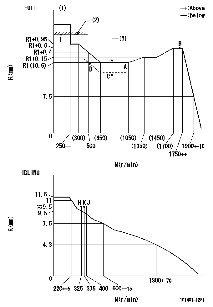
N:Pump speed
R:Rack position (mm)
(1)Torque cam stamping: T1
(2)RACK LIMIT
(3)Boost compensator stroke: BCL
----------
T1=B71 BCL=(0.6)+-0.1mm
----------
----------
T1=B71 BCL=(0.6)+-0.1mm
----------
Speed control lever angle
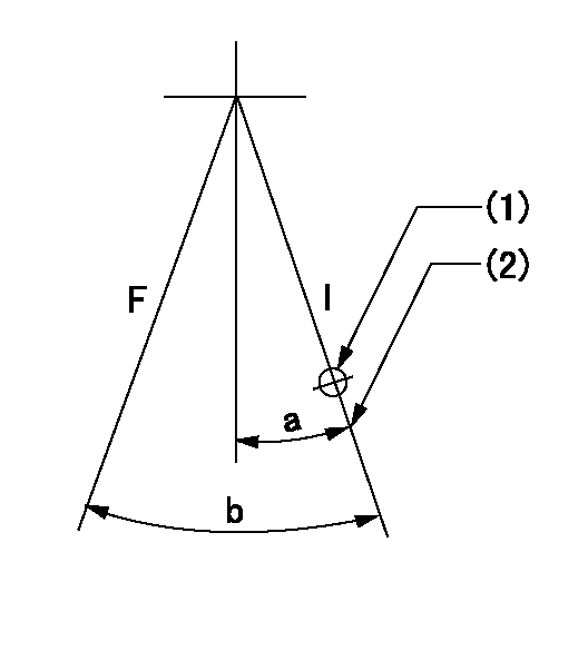
F:Full speed
I:Idle
(1)Use the hole at R = aa
(2)Stopper bolt set position 'K'
----------
aa=40mm
----------
a=26deg+-5deg b=42deg+-3deg
----------
aa=40mm
----------
a=26deg+-5deg b=42deg+-3deg
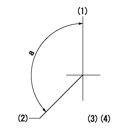
Stop lever angle
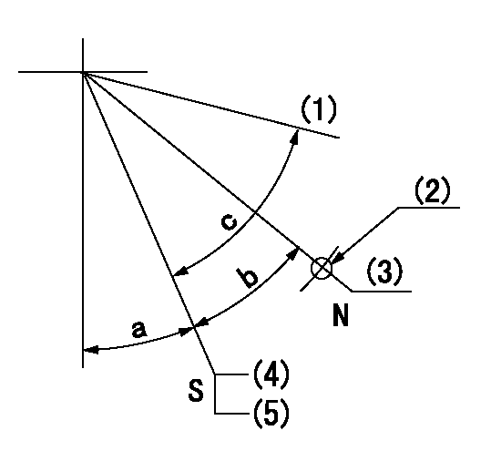
N:Engine manufacturer's normal use
S:Stop the pump.
(1)Free (at shipping)
(2)Use the hole at R = aa
(3)Rack position corresponding to bb
(4)Set the stopper bolt so that speed = cc and rack position = dd.
(5)After setting the stopper bolt, confirm non-injection at speed ee. (Rack position = ff or less)
----------
aa=40mm bb=16mm cc=1700r/min dd=6.5-0.5mm ee=375r/min ff=8mm
----------
a=8deg+-5deg b=15deg+-5deg c=25deg+-5deg
----------
aa=40mm bb=16mm cc=1700r/min dd=6.5-0.5mm ee=375r/min ff=8mm
----------
a=8deg+-5deg b=15deg+-5deg c=25deg+-5deg
0000001501 MICRO SWITCH
Adjustment of the micro-switch
Adjust the bolt to obtain the following lever position when the micro-switch is ON.
(1)Speed N1
(2)Rack position Ra
----------
N1=950+-5r/min Ra=8mm
----------
----------
N1=950+-5r/min Ra=8mm
----------
0000001601 ACTUATOR
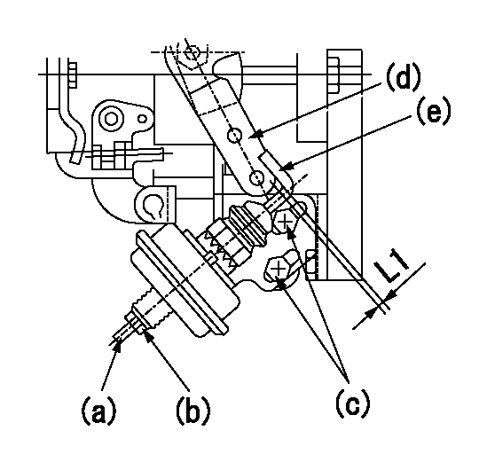
(a) Screw
(B) Nut
Bolt c
(d) Speed lever
(e) Actuator shaft
1. Actuator adjustment procedure
(1)Position the speed lever (d) in the idle position.
(2)Set bolt (c) so that the clearance between the speed lever (d)'s pin and the actuator shaft (e) is approximately L1.
(3)Loosen the nut (b) and fully tighten the screw (a).
(4)Set the pump speed at N1 and read the rack position when negative pressure P1 is applied to the actuator.
(5)Gradually loosen screw (a) and fix the nut (b) when the pump speed is N2 and the rack position is R1.
(6)Apply negative pressure several times and confirm that the lever (d) returns to the idle position at negative pressure '0.'
(7)Confirm that rack position is R2 when negative pressure is P2.
----------
L1=2mm N1=500r/min P1=66.7kPa(500mmHg) N2=500r/min R1=9.1mm P2=66.7kPa(500mmHg) R2=9.1mm
----------
----------
L1=2mm N1=500r/min P1=66.7kPa(500mmHg) N2=500r/min R1=9.1mm P2=66.7kPa(500mmHg) R2=9.1mm
----------
Timing setting
(1)Pump vertical direction
(2)Position of gear mark '3' at No 1 cylinder's beginning of injection
(3)B.T.D.C.: aa
(4)-
----------
aa=9.5deg
----------
a=(130deg)
----------
aa=9.5deg
----------
a=(130deg)