Rating:
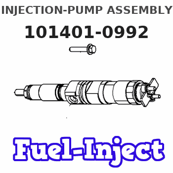
Information injection-pump assembly
BOSCH
9 400 613 594
9400613594
ZEXEL
101401-0992
1014010992
ISUZU
8970103244
8970103244
Service parts 101401-0992 INJECTION-PUMP ASSEMBLY:
1.
_
6.
COUPLING PLATE
7.
COUPLING PLATE
8.
_
9.
_
11.
Nozzle and Holder
8-94479-578-3
12.
Open Pre:MPa(Kqf/cm2)
21.6{220}

15.
NOZZLE SET
Cross reference number
BOSCH
9 400 613 594
9400613594
ZEXEL
101401-0992
1014010992
ISUZU
8970103244
8970103244
Zexel num
Bosch num
Firm num
Name
101401-0992
9 400 613 594
8970103244 ISUZU
INJECTION-PUMP ASSEMBLY
4BG1 * K
4BG1 * K
Calibration Data:
Adjustment conditions
Test oil
1404 Test oil ISO4113 or {SAEJ967d}
1404 Test oil ISO4113 or {SAEJ967d}
Test oil temperature
degC
40
40
45
Nozzle and nozzle holder
105780-8140
Bosch type code
EF8511/9A
Nozzle
105780-0000
Bosch type code
DN12SD12T
Nozzle holder
105780-2080
Bosch type code
EF8511/9
Opening pressure
MPa
17.2
Opening pressure
kgf/cm2
175
Injection pipe
Outer diameter - inner diameter - length (mm) mm 6-2-600
Outer diameter - inner diameter - length (mm) mm 6-2-600
Overflow valve
131424-4920
Overflow valve opening pressure
kPa
127
107
147
Overflow valve opening pressure
kgf/cm2
1.3
1.1
1.5
Tester oil delivery pressure
kPa
157
157
157
Tester oil delivery pressure
kgf/cm2
1.6
1.6
1.6
Direction of rotation (viewed from drive side)
Right R
Right R
Injection timing adjustment
Direction of rotation (viewed from drive side)
Right R
Right R
Injection order
1-3-4-2
Pre-stroke
mm
3.6
3.55
3.65
Rack position
Point A R=A
Point A R=A
Beginning of injection position
Drive side NO.1
Drive side NO.1
Difference between angles 1
Cal 1-3 deg. 90 89.5 90.5
Cal 1-3 deg. 90 89.5 90.5
Difference between angles 2
Cal 1-4 deg. 180 179.5 180.5
Cal 1-4 deg. 180 179.5 180.5
Difference between angles 3
Cyl.1-2 deg. 270 269.5 270.5
Cyl.1-2 deg. 270 269.5 270.5
Injection quantity adjustment
Adjusting point
-
Rack position
11.3
Pump speed
r/min
900
900
900
Average injection quantity
mm3/st.
69.6
68
71.2
Max. variation between cylinders
%
0
-4
4
Basic
*
Fixing the rack
*
Standard for adjustment of the maximum variation between cylinders
*
Injection quantity adjustment_02
Adjusting point
H
Rack position
9.5+-0.5
Pump speed
r/min
350
350
350
Average injection quantity
mm3/st.
9.8
8.5
11.1
Max. variation between cylinders
%
0
-14
14
Fixing the rack
*
Standard for adjustment of the maximum variation between cylinders
*
Injection quantity adjustment_03
Adjusting point
A
Rack position
R1(11.3)
Pump speed
r/min
900
900
900
Average injection quantity
mm3/st.
69.6
68.6
70.6
Basic
*
Fixing the lever
*
Injection quantity adjustment_04
Adjusting point
B
Rack position
R1+0.15
Pump speed
r/min
1525
1525
1525
Average injection quantity
mm3/st.
82.1
78.9
85.3
Fixing the lever
*
Injection quantity adjustment_05
Adjusting point
C
Rack position
R1(11.3)
Pump speed
r/min
600
600
600
Average injection quantity
mm3/st.
53.1
49.9
56.3
Fixing the lever
*
Injection quantity adjustment_06
Adjusting point
I
Rack position
-
Pump speed
r/min
150
150
150
Average injection quantity
mm3/st.
86
78
94
Fixing the lever
*
Timer adjustment
Pump speed
r/min
1370--
Advance angle
deg.
0
0
0
Remarks
Start
Start
Timer adjustment_02
Pump speed
r/min
1320
Advance angle
deg.
0.3
Timer adjustment_03
Pump speed
r/min
1600
Advance angle
deg.
5
4.5
5.5
Remarks
Finish
Finish
Test data Ex:
Governor adjustment
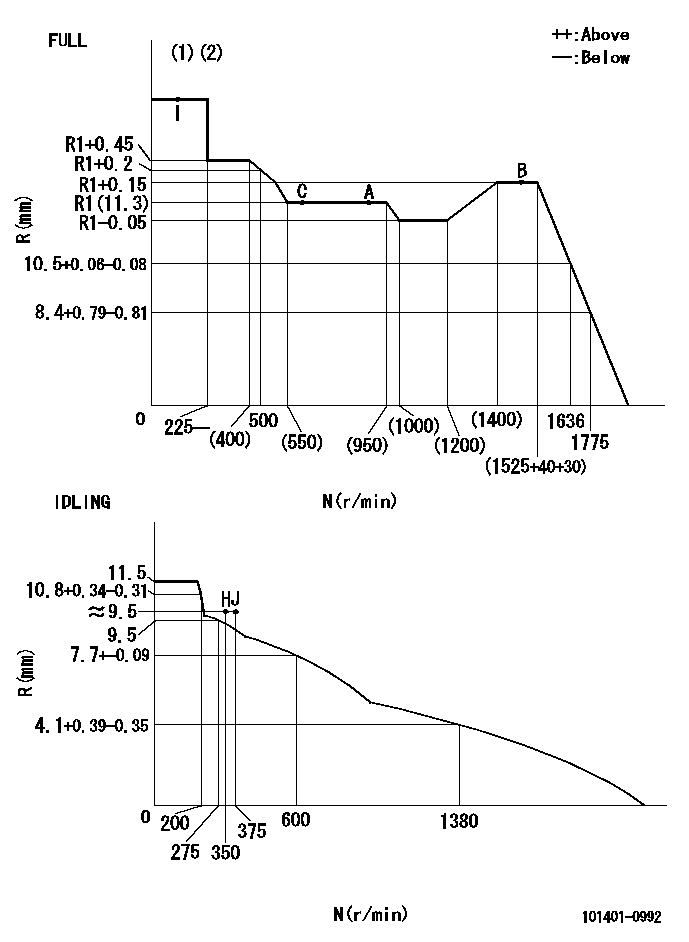
N:Pump speed
R:Rack position (mm)
(1)Torque cam stamping: T1
(2)Tolerance for racks not indicated: +-0.05mm.
----------
T1=D65
----------
----------
T1=D65
----------
Speed control lever angle
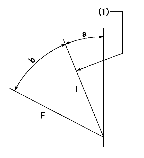
F:Full speed
I:Idle
(1)Stopper bolt set position 'H'
----------
----------
a=4.5deg+-5deg b=(31.5deg)+-3deg
----------
----------
a=4.5deg+-5deg b=(31.5deg)+-3deg
0000001501 FICD
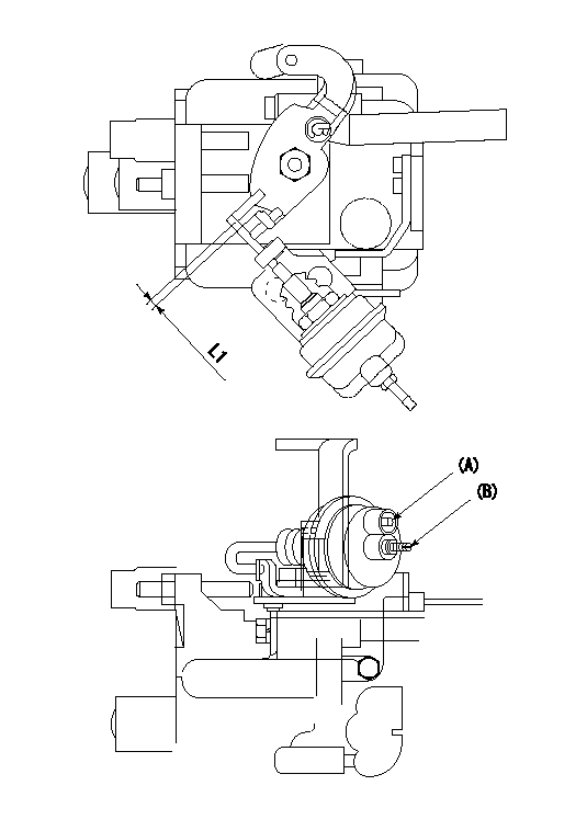
Negative pressure port A
(B) Screw
1. FICD adjustment
(1)Set the clearance between the actuator and the speed lever at L1.
(2)Fully screw in screw B.
(3)Apply P1 to negative pressure port A and gradually tighten screw B.
(4)Fix the screw (B) at pump speed N1 and rack position R1. (Tightening torque = T1)
(5)Apply P2 to negative pressure port A and confirm that the FICD operates normally.
----------
L1=(3)mm P1=53.3kPa(400mmHg) P2=53.3kPa(400mmHg) N1=600r/min R1=9.2+-0.1mm
----------
----------
L1=(3)mm P1=53.3kPa(400mmHg) P2=53.3kPa(400mmHg) N1=600r/min R1=9.2+-0.1mm
----------
Timing setting
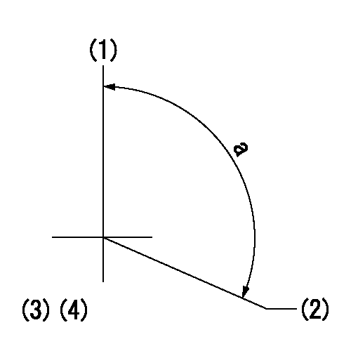
(1)Pump vertical direction
(2)Position of gear mark 'CC' at No 1 cylinder's beginning of injection
(3)-
(4)-
----------
----------
a=(100deg)
----------
----------
a=(100deg)
Have questions with 101401-0992?
Group cross 101401-0992 ZEXEL
Isuzu
101401-0992
9 400 613 594
8970103244
INJECTION-PUMP ASSEMBLY
4BG1
4BG1