Rating:
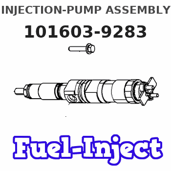
Information injection-pump assembly
BOSCH
9 400 615 293
9400615293
ZEXEL
101603-9283
1016039283
DAEWOO
65111017239
65111017239
Service parts 101603-9283 INJECTION-PUMP ASSEMBLY:
1.
_
7.
COUPLING PLATE
8.
_
9.
_
10.
NOZZLE AND HOLDER ASSY
11.
Nozzle and Holder
12.
Open Pre:MPa(Kqf/cm2)
13.
NOZZLE-HOLDER
14.
NOZZLE
15.
NOZZLE SET
Cross reference number
BOSCH
9 400 615 293
9400615293
ZEXEL
101603-9283
1016039283
DAEWOO
65111017239
65111017239
Zexel num
Bosch num
Firm num
Name
101603-9283
9 400 615 293
65111017239 DAEWOO
INJECTION-PUMP ASSEMBLY
D1146 * K
D1146 * K
Calibration Data:
Adjustment conditions
Test oil
1404 Test oil ISO4113 or {SAEJ967d}
1404 Test oil ISO4113 or {SAEJ967d}
Test oil temperature
degC
40
40
45
Nozzle and nozzle holder
105780-8140
Bosch type code
EF8511/9A
Nozzle
105780-0000
Bosch type code
DN12SD12T
Nozzle holder
105780-2080
Bosch type code
EF8511/9
Opening pressure
MPa
17.2
Opening pressure
kgf/cm2
175
Injection pipe
Outer diameter - inner diameter - length (mm) mm 6-2-600
Outer diameter - inner diameter - length (mm) mm 6-2-600
Overflow valve
131424-1520
Overflow valve opening pressure
kPa
157
123
191
Overflow valve opening pressure
kgf/cm2
1.6
1.25
1.95
Tester oil delivery pressure
kPa
157
157
157
Tester oil delivery pressure
kgf/cm2
1.6
1.6
1.6
Direction of rotation (viewed from drive side)
Right R
Right R
Injection timing adjustment
Direction of rotation (viewed from drive side)
Right R
Right R
Injection order
6-2-4-1-
5-3
Pre-stroke
mm
4.6
4.55
4.65
Beginning of injection position
Drive side NO.1
Drive side NO.1
Difference between angles 1
Cal 6-2 deg. 60 59.5 60.5
Cal 6-2 deg. 60 59.5 60.5
Difference between angles 2
Cal 6-4 deg. 120 119.5 120.5
Cal 6-4 deg. 120 119.5 120.5
Difference between angles 3
Cal 6-1 deg. 180 179.5 180.5
Cal 6-1 deg. 180 179.5 180.5
Difference between angles 4
Cal 6-5 deg. 240 239.5 240.5
Cal 6-5 deg. 240 239.5 240.5
Difference between angles 5
Cal 6-3 deg. 300 299.5 300.5
Cal 6-3 deg. 300 299.5 300.5
Injection quantity adjustment
Adjusting point
-
Rack position
11.4
Pump speed
r/min
700
700
700
Average injection quantity
mm3/st.
74.8
73.2
76.4
Max. variation between cylinders
%
0
-2
2
Basic
*
Fixing the rack
*
Standard for adjustment of the maximum variation between cylinders
*
Injection quantity adjustment_02
Adjusting point
H
Rack position
10.2+-0.
5
Pump speed
r/min
250
250
250
Average injection quantity
mm3/st.
17
15.5
18.5
Max. variation between cylinders
%
0
-15
15
Fixing the rack
*
Standard for adjustment of the maximum variation between cylinders
*
Injection quantity adjustment_03
Adjusting point
A
Rack position
R1(11.4)
Pump speed
r/min
700
700
700
Average injection quantity
mm3/st.
74.8
73.8
75.8
Basic
*
Fixing the lever
*
Injection quantity adjustment_04
Adjusting point
B
Rack position
R1+0.1
Pump speed
r/min
1250
1250
1250
Average injection quantity
mm3/st.
80.2
76.2
84.2
Fixing the lever
*
Injection quantity adjustment_05
Adjusting point
C
Rack position
R1-0.25
Pump speed
r/min
500
500
500
Average injection quantity
mm3/st.
58.4
54.4
62.4
Fixing the lever
*
Injection quantity adjustment_06
Adjusting point
I
Rack position
-
Pump speed
r/min
100
100
100
Average injection quantity
mm3/st.
115
115
130
Fixing the lever
*
Rack limit
*
Timer adjustment
Pump speed
r/min
950--
Advance angle
deg.
0
0
0
Remarks
Start
Start
Timer adjustment_02
Pump speed
r/min
900
Advance angle
deg.
0.5
Timer adjustment_03
Pump speed
r/min
1250
Advance angle
deg.
4
3.5
4.5
Remarks
Finish
Finish
Test data Ex:
Governor adjustment
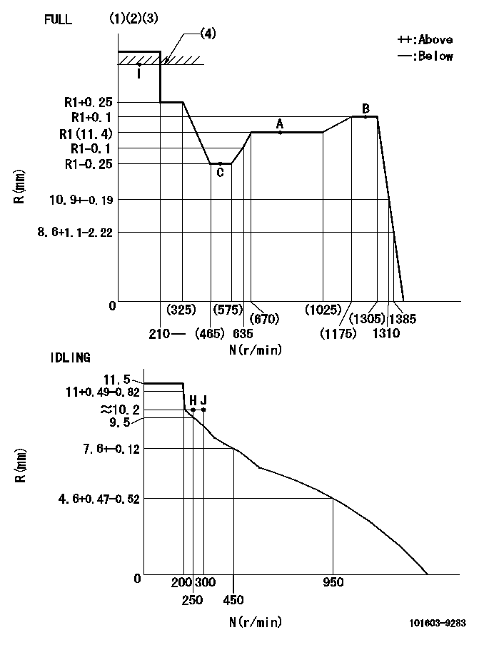
N:Pump speed
R:Rack position (mm)
(1)Torque cam stamping: T1
(2)Tolerance for racks not indicated: +-0.05mm.
(3)Microswitch adjustment unnecessary.
(4)RACK LIMIT
----------
T1=D58
----------
----------
T1=D58
----------
Speed control lever angle
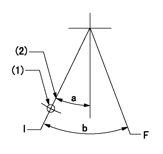
F:Full speed
I:Idle
(1)Use the hole at R = aa
(2)Stopper bolt set position 'H'
----------
aa=65mm
----------
a=24deg+-5deg b=37deg+-3deg
----------
aa=65mm
----------
a=24deg+-5deg b=37deg+-3deg
Stop lever angle
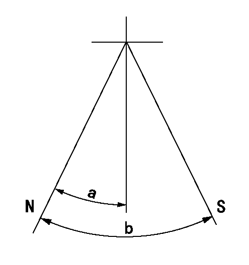
N:Pump normal
S:Stop the pump.
----------
----------
a=25deg+-5deg b=40deg+-5deg
----------
----------
a=25deg+-5deg b=40deg+-5deg
Timing setting
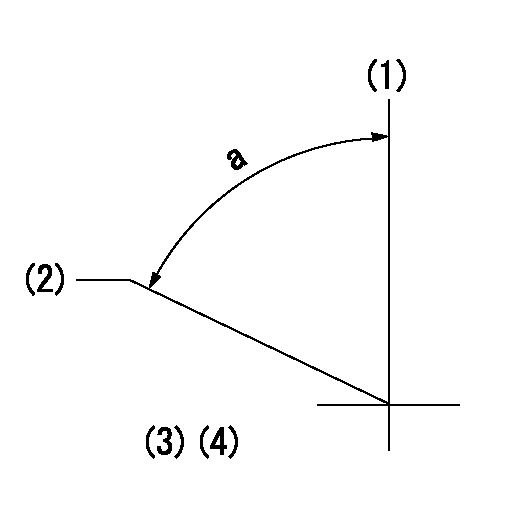
(1)Pump vertical direction
(2)Coupling's key groove position for the No. 6 cylinder's beginning of injection
(3)-
(4)-
----------
----------
a=(60deg)
----------
----------
a=(60deg)
Have questions with 101603-9283?
Group cross 101603-9283 ZEXEL
Nissan-Diesel
Dpico
Yanmar
Daewoo
101603-9283
9 400 615 293
65111017239
INJECTION-PUMP ASSEMBLY
D1146
D1146