Information control unit
BOSCH
F 01G 09P 0D6
f01g09p0d6
ZEXEL
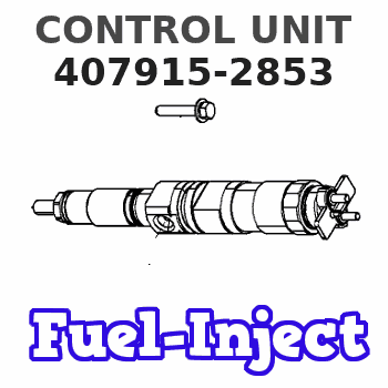
407915-2853
4079152853
Rating:
Compare Prices: .
As an associate, we earn commssions on qualifying purchases through the links below

$1,880.00
07 Jul 2022
8.8184[3.97] Pounds
US: Jin cheng excavator
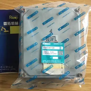
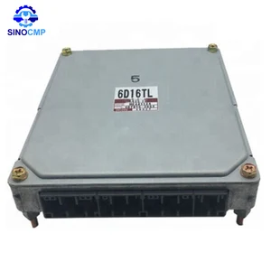
SK330-6E excavator 6D16L engine ME441124 controller control board box computer panel 407915-2852
jinchengparts
jinchengparts

$2,619.90
25 Jun 2022
8.8184[3.97] Pounds
CN: SINOCMP Excavator Pa
SINOCMP ME441124 Diesel Fuel Pump Controller for Kobelco SK330-6E SK350-6E SK450-6 Fuel Pump Controller
SINOCMP SINOCMP Diesel Fuel Pump Controller ME441124 for Kobelco SK330-6E SK350-6E SK450-6 || Part Number: ME441124 || Model Number: SK330-6E SK350-6E SK450-6 || Warranty: 1 year || SINOCMP Diesel Fuel Pump Controller ME441124 for Kobelco SK330-6E SK350-6E SK450-6
SINOCMP SINOCMP Diesel Fuel Pump Controller ME441124 for Kobelco SK330-6E SK350-6E SK450-6 || Part Number: ME441124 || Model Number: SK330-6E SK350-6E SK450-6 || Warranty: 1 year || SINOCMP Diesel Fuel Pump Controller ME441124 for Kobelco SK330-6E SK350-6E SK450-6
$1,880.00
29 May 2021
8.8184[3.97] Pounds
CN: Jin cheng excavator
SK330-6E excavator 6D16L engine ME441124 controller control board box computer panel 407915-2852
beyondparts
beyondparts
You can express buy:

USD 986.6
14-06-2025
14-06-2025
Original SK330-6E Engine Controller, 6D16 6D16TL Computer Board Controller ME441124 LC27E00067F7
USD 1150
23-05-2025
23-05-2025
Original SK330-6E Engine Controller, 6D16 6D16TL Computer Board Controller ME441124 LC27E00067F7
USD 5518.76
13-05-2025
13-05-2025
6D16T Original Engine Controller ME441124 For Kobelco SK330-6E SK350-6E Excavator
Images:
USD 560

[10-May-2025]
Cross reference number
Zexel num
Bosch num
Firm num
Name
407915-2853
F 01G 09P 0D6
CONTROL UNIT
74PD CONTROL UNIT C/U N-RED3 C/U PE
74PD CONTROL UNIT C/U N-RED3 C/U PE
F 01G 09P 0D6
ME441124 MITSUBISHI
CONTROL UNIT
* C 74PD CONTROL UNIT C/U N-RED3 C/U PE
* C 74PD CONTROL UNIT C/U N-RED3 C/U PE
Information:
No-load testAlternator
If a problem occurs in the charge system, check the following conditions to locate the cause of the problem. Only when inspection cannot be conducted on the alternator in the installed condition, dismount the alternator for inspection and repair. On Vehicle Inspection
(1) Cautions for handlingHandle the alternator carefully, as incorrect handling can result in alternator damage or malfunctions.(a) Do not connect the battery cables in reverse. Note the negative (-) cable is a grounding wire.(b) Do not use a high-voltage tester such as a megger.(c) When charging the battery, disconnect the cables from the battery terminals.(d) Do not disconnect the lead wire from terminal B of the alternator while the engine is operating.(e) Do not ground terminal B of the alternator since it is constantly applied with battery voltage.(f) Do not short-circuit or ground terminal L. (unit with integrated IC regulator)(g) When using a steam cleaner, do not allow steam to directly contact the alternator.(2) Inspection of adjustment voltage (unit with integrated IC regulator)(a) Disconnect the cable from the positive (+) terminal of the battery, and connect an ammeter between the terminal and cable.(b) Connect a voltmeter between terminal L and ground.(c) Make sure that the voltmeter indicates "0" when the starter switch is turned off. Make sure that the voltmeter indicates a voltage level significantly lower than the battery voltage when the starter switch is turned on (without starting the engine).(d) Short-circuit the terminal of the ammeter, and start the engine.(e) Read the indication (adjustment voltage) on the voltmeter with the ammeter indicating 5A or lower, the engine operating at 1500 to 2500 min-1, and the lamp switches turned off.
Inspection of adjustment voltage (3) Inspection of output (unit with integrated IC regulator)(a) Disconnect the grounding cable from the battery.(b) Disconnect the wire from terminal B of the alternator, and connect an ammeter, then connect a voltmeter between B and ground.(c) Reconnect the grounding cable to the battery.(d) Start the engine.(e) Immediately after the engine starts, turn on all load devices such as lamps.(f) Increase the engine speed, and read the maximum current at the specified alternator rotation speed when the voltmeter indicates 27.0 V. If the measured value conforms to the standard value, the alternator is normal.
Wiring for output test (unit with integrated IC regulator) Disassembly of Alternator
(1) Separation of front bracket from stator coreInsert the tip of a slotted screwdriver into the gap between the stator core and front bracket, and pry open.
Do not insert the screwdriver too far into the assembly to prevent damaging the stator core.
Separation of front bracket from stator core(2) Removal of pulley(a) After wrapping the rotor with a cloth for protection and holding it with a vice, unscrew the pulley nut, then remove the pulley and spacer.(b) Remove the rotor from the front bracket.
Removal of pulley(3) Removal of stator core and rectifier(a) Disconnect the lead wires between the stator core and the rectifier at the soldered sections, and remove the stator core.
Melt the soldered sections as quickly as possible. Prolonged
Have questions with 407915-2853?
Group cross 407915-2853 ZEXEL
Mitsubishi
407915-2853
F 01G 09P 0D6
CONTROL UNIT