
Rating:
Information injection-pump assembly
ZEXEL
104749-6440
1047496440
ISUZU
8944189140
8944189140
Cross reference number
ZEXEL
104749-6440
1047496440
ISUZU
8944189140
8944189140
Zexel num
Bosch num
Firm num
Name
Calibration Data:
Adjustment conditions
Test oil
1404 Test oil ISO4113orSAEJ967d
1404 Test oil ISO4113orSAEJ967d
Test oil temperature
degC
45
45
50
Nozzle
105000-2010
Bosch type code
NP-DN12SD12TT
Nozzle holder
105780-2080
Opening pressure
MPa
14.7
14.7
15.19
Opening pressure
kgf/cm2
150
150
155
Injection pipe
Inside diameter - outside diameter - length (mm) mm 2-6-840
Inside diameter - outside diameter - length (mm) mm 2-6-840
Transfer pump pressure
kPa
20
20
20
Transfer pump pressure
kgf/cm2
0.2
0.2
0.2
Direction of rotation (viewed from drive side)
Right R
Right R
Injection timing adjustment
Pump speed
r/min
1250
1250
1250
Average injection quantity
mm3/st.
38.7
37.7
39.7
Difference in delivery
mm3/st.
3
Basic
*
Injection timing adjustment_02
Pump speed
r/min
2650
2650
2650
Average injection quantity
mm3/st.
12.1
8.6
15.6
Injection timing adjustment_03
Pump speed
r/min
2350
2350
2350
Average injection quantity
mm3/st.
33.1
31
35.2
Injection timing adjustment_04
Pump speed
r/min
2250
2250
2250
Average injection quantity
mm3/st.
33.2
31.2
35.2
Injection timing adjustment_05
Pump speed
r/min
2000
2000
2000
Average injection quantity
mm3/st.
33.7
31.7
35.7
Injection timing adjustment_06
Pump speed
r/min
1250
1250
1250
Average injection quantity
mm3/st.
38.2
37.2
39.2
Injection timing adjustment_07
Pump speed
r/min
600
600
600
Average injection quantity
mm3/st.
37.2
35.2
39.2
Injection quantity adjustment
Pump speed
r/min
2650
2650
2650
Average injection quantity
mm3/st.
12.1
9.1
15.1
Difference in delivery
mm3/st.
4
Basic
*
Injection quantity adjustment_02
Pump speed
r/min
2800
2800
2800
Average injection quantity
mm3/st.
5
Governor adjustment
Pump speed
r/min
400
400
400
Average injection quantity
mm3/st.
8.8
6.8
10.8
Difference in delivery
mm3/st.
2
Basic
*
Governor adjustment_02
Pump speed
r/min
400
400
400
Average injection quantity
mm3/st.
8.8
6.8
10.8
Governor adjustment_03
Pump speed
r/min
575
575
575
Average injection quantity
mm3/st.
3
Timer adjustment
Pump speed
r/min
100
100
100
Average injection quantity
mm3/st.
75
60
90
Basic
*
Speed control lever angle
Pump speed
r/min
400
400
400
Average injection quantity
mm3/st.
0
0
0
Remarks
Magnet OFF
Magnet OFF
0000000901
Pump speed
r/min
1250
1250
1250
Overflow quantity
cm3/min
420
290
550
Stop lever angle
Pump speed
r/min
1250
1250
1250
Pressure
kPa
431.5
412
451
Pressure
kgf/cm2
4.4
4.2
4.6
Basic
*
Stop lever angle_02
Pump speed
r/min
600
600
600
Pressure
kPa
255
226
284
Pressure
kgf/cm2
2.6
2.3
2.9
Stop lever angle_03
Pump speed
r/min
1250
1250
1250
Pressure
kPa
431.5
412
451
Pressure
kgf/cm2
4.4
4.2
4.6
Stop lever angle_04
Pump speed
r/min
2000
2000
2000
Pressure
kPa
627.5
598
657
Pressure
kgf/cm2
6.4
6.1
6.7
Stop lever angle_05
Pump speed
r/min
2050
2050
2050
Pressure
kPa
637.5
608
667
Pressure
kgf/cm2
6.5
6.2
6.8
0000001101
Pump speed
r/min
1250
1250
1250
Timer stroke
mm
3.9
3.7
4.1
Basic
*
_02
Pump speed
r/min
1250
1250
1250
Timer stroke
mm
3.9
3.6
4.2
_03
Pump speed
r/min
1750
1750
1750
Timer stroke
mm
6.6
6
7.2
_04
Pump speed
r/min
2050
2050
2050
Timer stroke
mm
8.2
7.8
8.6
0000001201
Max. applied voltage
V
8
8
8
Test voltage
V
13
12
14
0000001401
Pump speed
r/min
1250
1250
1250
Average injection quantity
mm3/st.
33
32.5
33.5
Timer stroke variation dT
mm
0.9
0.7
1.1
Basic
*
_02
Pump speed
r/min
1250
1250
1250
Average injection quantity
mm3/st.
33
32
34
Timer stroke variation dT
mm
0.9
0.6
1.2
_03
Pump speed
r/min
1250
1250
1250
Average injection quantity
mm3/st.
25
23.5
26.5
Timer stroke variation dT
mm
1.6
1.1
2.1
0000001501
Pump speed
r/min
1250
1250
1250
Atmospheric pressure difference
kPa
-21.9
-22.6
-21.2
Atmospheric pressure difference
mmHg
-164
-169
-159
Decrease qty
mm3/st.
3.8
2.8
4.8
Basic
*
_02
Pump speed
r/min
1250
1250
1250
Atmospheric pressure difference
kPa
-21.9
-22.6
-21.2
Atmospheric pressure difference
mmHg
-164
-169
-159
Decrease qty
mm3/st.
3.8
2.1
5.5
Timing setting
K dimension
mm
3.3
3.2
3.4
KF dimension
mm
5.8
5.7
5.9
MS dimension
mm
1.6
1.5
1.7
Control lever angle alpha
deg.
24.5
20.5
28.5
Control lever angle beta
deg.
40.5
35.5
45.5
Test data Ex:
0000001501 ANEROID COMPENSATOR
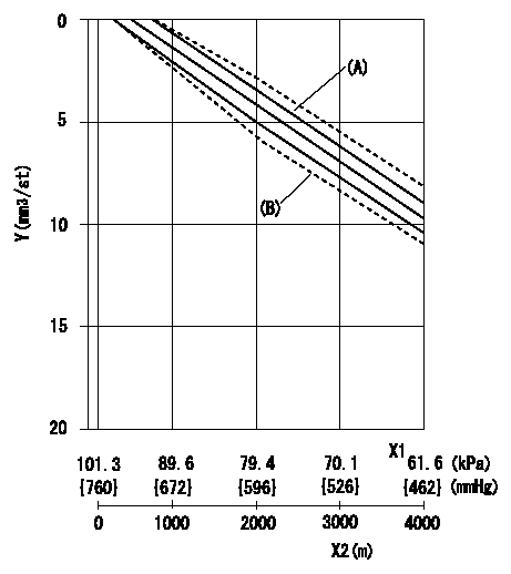
ACS adjustment
Full load injection quantity at high altitudes and ACS adjusting method
1. Full load injection quantity adjustment
(1)Remove the ACS cover and remove the bellows and adjusting shim.
(2)Perform all adjustments as per the adjustment standard except for ACS adjustment.
2. ACS adjustment
(1)Assemble the ACS cover, bellows and adjusting shim.
(2)At pump speed N1, adjust using a shim to obtain the decrease for the altitude shown in the table.
X1 = atmospheric pressure
X2 = altitude
Y = decrease quantity
(A) = adjustment value
(B) = test value
----------
N1=1250r/min
----------
----------
N1=1250r/min
----------
0000001801 W-CSD ADJUSTMENT
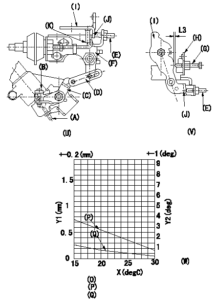
Adjustment of the W-CSD
1. CSD adjusting screw adjustment
Adjust so that the adjusting screw (A) protrusion is L1, then confirm. (U)
2. Adjustment of the position of the intermediate lever.
Insert a shim L2 between the control lever (I) and the FICD screw (E).
With the shim inserted, insert a shim L3 between the control lever (I) and the idle set screw (G). Align intermediate lever (F) with the aligning mark and fix screw (E) so that it contacts the control lever. [(U), (V)]
3. Adjustment of the FICD
With a shim L2 inserted, insert a shim L4 between the control lever and the idle set screw (G).
Use adjusting screw (B) to fix the CSD lever (C) in the position where it operates the intermediate lever (F) via the rod (D). [(U), (V), (W)]
(P) = Lever angle (deg): theta = 0.1925t+6.65
(Q) = Lever position (mm): L = -0.0635t+2.19
(R) = (Q) shows the distance between the control lever and the idle set screw.
X = temperature t
Y1 = timer stroke TA
Y2 = control lever angle theta, L (deg, mm)
(K) = aligning mark
(U) = diagram 1
(V) = diagram 2
(W) = diagram 3
----------
L1=10.2mm L2=2.8+-0.05mm L3=0.92+-0.05mm L4=L3+-0.05mm
----------
----------
L1=10.2mm L2=2.8+-0.05mm L3=0.92+-0.05mm L4=L3+-0.05mm
----------