
Rating:
Information
ZEXEL
106662-2040
1066622040
MITSUBISHI-HEAV
0429050191
0429050191
Service parts 106662-2040 INJECTION-PUMP ASSEMBLY:
1.
_
2.
FUEL INJECTION PUMP
5.
AUTOM. ADVANCE MECHANIS
6.
COUPLING PLATE
7.
COUPLING PLATE
8.
_
9.
_
10.
NOZZLE AND HOLDER ASSY
11.
Nozzle and Holder
12.
Open Pre:MPa(Kqf/cm2)
13.
NOZZLE-HOLDER
14.
NOZZLE
15.
NOZZLE SET
Include in #1:
106662-2040
as INJECTION-PUMP ASSEMBLY
Cross reference number
ZEXEL
106662-2040
1066622040
MITSUBISHI-HEAV
0429050191
0429050191
Zexel num
Bosch num
Firm num
Name
Calibration Data:
Adjustment conditions
Test oil
1404 Test oil ISO4113 or {SAEJ967d}
1404 Test oil ISO4113 or {SAEJ967d}
Test oil temperature
degC
40
40
45
Nozzle
105780-0020
Bosch type code
DN4SD24T
Nozzle holder
105031-2010
Bosch type code
KB56SD273
Opening pressure
MPa
11.8
Opening pressure
kgf/cm2
120
Injection pipe
Outer diameter - inner diameter - length (mm) mm 6-2-600
Outer diameter - inner diameter - length (mm) mm 6-2-600
Overflow valve
132424-0620
Overflow valve opening pressure
kPa
157
123
191
Overflow valve opening pressure
kgf/cm2
1.6
1.25
1.95
Tester oil delivery pressure
kPa
157
157
157
Tester oil delivery pressure
kgf/cm2
1.6
1.6
1.6
Direction of rotation (viewed from drive side)
Right R
Right R
Injection timing adjustment
Direction of rotation (viewed from drive side)
Right R
Right R
Injection order
1-5-3-6-
2-4
Pre-stroke
mm
2.05
2
2.1
Beginning of injection position
Drive side NO.1
Drive side NO.1
Difference between angles 1
Cal 1-5 deg. 60 59.5 60.5
Cal 1-5 deg. 60 59.5 60.5
Difference between angles 2
Cal 1-3 deg. 120 119.5 120.5
Cal 1-3 deg. 120 119.5 120.5
Difference between angles 3
Cal 1-6 deg. 180 179.5 180.5
Cal 1-6 deg. 180 179.5 180.5
Difference between angles 4
Cyl.1-2 deg. 240 239.5 240.5
Cyl.1-2 deg. 240 239.5 240.5
Difference between angles 5
Cal 1-4 deg. 300 299.5 300.5
Cal 1-4 deg. 300 299.5 300.5
Injection quantity adjustment
Adjusting point
A
Rack position
18+-0.5
Pump speed
r/min
900
900
900
Average injection quantity
mm3/st.
280
272
288
Max. variation between cylinders
%
0
-3
3
Basic
*
Fixing the rack
*
Injection quantity adjustment_02
Adjusting point
B
Rack position
6.5+-0.5
Pump speed
r/min
250
250
250
Average injection quantity
mm3/st.
35
31.5
38.5
Max. variation between cylinders
%
0
-10
10
Fixing the rack
*
Test data Ex:
Governor adjustment
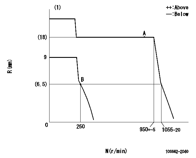
N:Pump speed
R:Rack position (mm)
(1)Target notch: K
----------
K=10
----------
----------
K=10
----------
Speed control lever angle
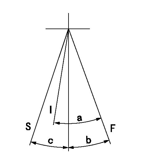
F:Full speed
I:Idle
S:Stop
----------
----------
a=33deg+-5deg b=8deg+-5deg c=32deg+-3deg
----------
----------
a=33deg+-5deg b=8deg+-5deg c=32deg+-3deg
Stop lever angle
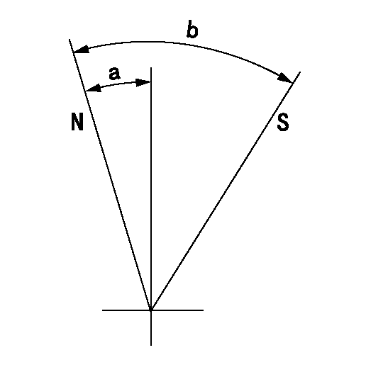
N:Pump normal
S:Stop the pump.
----------
----------
a=(11deg) b=(53deg)
----------
----------
a=(11deg) b=(53deg)